The Second Los Angeles Aqueduct - 1970
 |
|
| (2011)* - Terminus of the First and Second Los Angeles Aqueducts in Sylmar. Photo: Perplexity |
First Los Angeles Aqueduct and Mono Basin Extension The First Los Angeles Aqueduct was completed in 1913, delivering water 233 miles from the Owens River to the city. In the 1930s, the Department of Water and Power expanded its reach northward into the Mono Basin. This led to the construction of the Mono Basin Extension, completed in 1941, which increased the total aqueduct system length to 338 miles. The extension allowed Los Angeles to divert additional Eastern Sierra sources, including streams that fed Mono Lake. |
Conception of the Second Los Angeles Aqueduct The original aqueduct system often operated at capacity when runoff was sufficient, but it faced both periods of surplus and drought. The Mono Basin Extension, completed in 1941, helped ensure full-capacity operation even during dry years. However, the city’s water rights filings—and the added capacity from the Mono Basin Extension—exceeded what the original aqueduct could reliably deliver, prompting serious consideration of a second aqueduct to fully utilize these entitlements. By the late 1960s, Los Angeles could no longer divert its full Mono Basin entitlement on a sustained basis without additional conveyance. State agencies urged the city to act or risk losing its rights. Meanwhile, the 1963 U.S. Supreme Court decision in Arizona v. California reduced Los Angeles’s access to Colorado River water. As a result, Eastern Sierra water—superior in both quality and availability—became increasingly attractive, particularly given its lower delivery costs compared to Metropolitan Water District imports. |
 |
|
| (1971)* - Map showing both Original and the Second Los Angeles Aqueducts as they virtually parallel each other all the way from Haiwee Reservoir down to their terminus in Sylmar at the northeast end of the San Fernando Valley. |
Construction of the Second Aqueduct The Second Los Angeles Aqueduct, managed by the Los Angeles Department of Water and Power and primarily constructed by private contractors, began construction in 1965 and was completed in 1970 at a cost of $89 million. Starting at Haiwee Reservoir just south of the Owens dry lake bed, the new aqueduct was designed to be shorter and half as wide as Mulholland’s original aqueduct, making it easier to build due to advancements in construction equipment and the lower cost of steel pipe at the time. |
Archive DWP Images
 |
||
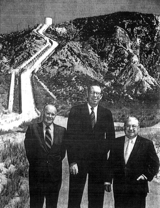
| (ca. 1970)* - John G. Cowan (Assistant General Manager and Chief Engineer), Robert V. Phillips (Chief Engineer of Water Works and Assistant General Manager), and Edgar L. Kanouse (General Manager and Chief Engineer), left to right, pictured below the Cascades at the newly completed Second Aqueduct. |
Historical Notes When it became operational in 1970, the Second Aqueduct increased the city’s water delivery capacity by about 50%, effectively doubling the amount of water that could be transported to Los Angeles compared to the original system. This expansion was crucial for the city to secure and fully utilize its permitted water rights from the Owens Valley and Mono Basin, ensuring a more reliable and robust water supply to meet the growing needs of Los Angeles. The increased flows provided by the second aqueduct lasted only from 1971 through 1988. In 1974 the environmental consequences of the higher exports were first being recognized in the Mono Basin and Owens Valley. This was followed by a series of court ordered restrictions imposed on water exports, which resulted in Los Angeles losing water. In 2005, the Los Angeles Urban Water Management Report reported that forty to fifty percent of the aqueduct's historical supply is now devoted to ecological resources in Mono and Inyo counties. |
 |
|
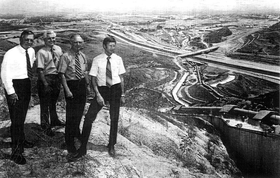
| (ca. 1970)* – William J. Simon, Roland Triay Jr., Joseph Siegel, and Duane L. Georgeson (l to r) observe the Terminal Structure of the Second Aqueduct as it releases approximately 300 cubic feet per second (cfs) down the Cascades into the Upper Van Norman Reservoir. At right, the original aqueduct can be seen flowing down the historic Cascades before both streams merge into a common channel. |
Historical Notes The Second Aqueduct Cascades start about 350 feet higher in elevation than the original Los Angeles Aqueduct Cascades. This elevation difference allows the second system to generate additional hydroelectric power and manage water flow more effectively as it enters the Los Angeles Basin. At the base of the cascades in Sylmar, each aqueduct is paired with its own hydroelectric power plant: the original Los Angeles Aqueduct is served by the San Fernando Power Plant, while the Second Aqueduct is associated with the Foothill Power Plant. The San Fernando Power Plant has a generating capacity of approximately 8.8 megawatts (MW), and the Foothill Power Plant, serving the Second Aqueduct, has a capacity of about 9.0 MW. Both plants utilize the steep elevation drop to efficiently convert the water’s potential energy into renewable electricity for Los Angeles, while also managing the delivery of water into the basin. |
 |
|
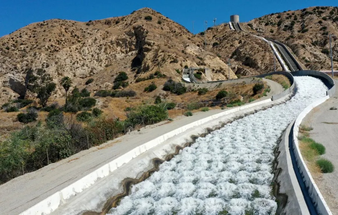
| (2006)* - The Cascades of the Second Los Angeles Aqueduct descend steeply into Sylmar. At left, the First Aqueduct’s flow is also visible. Note the large above-ground pipe (penstock) running parallel to the cascades, and the cylindrical surge tank positioned at the top of the hill. Photo by Mike Dillon / Wikipedia. |
Historical Notes The surge tank at the top of the Second Los Angeles Aqueduct cascades is designed to manage sudden changes in water pressure as water descends steeply through the penstock toward the hydroelectric plant and the Sylmar Cascades. By acting as a buffer, the surge tank absorbs excess pressure during rapid flow changes—such as when valves are quickly closed or opened—thereby preventing potentially damaging hydraulic shocks, known as water hammer, within the aqueduct system. This mechanism protects both the pipeline and hydroelectric infrastructure, ensuring stable and controlled water delivery to Los Angeles. There are two hydroelectric plants located in close proximity to their respective cascades, each being fed by water through penstocks running parallel to the cascades. The original San Fernando Power Plant is situated at the bottom of the original Los Angeles Aqueduct Cascades, within the Van Norman Complex, where the aqueduct makes its final descent into the Los Angeles Basin. Similarly, the Foothill Hydroelectric Power Plant, associated with the Second Los Angeles Aqueduct, is located near the top of Terminal Hill and adjacent to the Second Aqueduct Cascades, which start about 350 feet higher in elevation than the original cascades. Both plants utilize these penstocks to channel water for power generation, integrating closely with the cascades' water flow and hydraulic design. |
 |
|
| (2013)* – Close-up view of the dry Second Aqueduct Cascades, with its adjacent above-ground penstock pipe and surge tank at the top of the hill—a stark reminder of how scarce water can be in Southern California. Photo by Damian Dovarganes / AP. |
Historical Notes Water flows down the cascades of both the original and Second Los Angeles Aqueducts mainly when their respective hydroelectric power plants are offline for maintenance or when excess water exceeds the plants’ capacity. Normally, water is directed through penstocks to the San Fernando Power Plant (original aqueduct) and the Foothill Power Plant (second aqueduct), where it generates electricity before entering the reservoir system. When the plants cannot process the full flow, water is safely diverted to spill down the cascades, providing a controlled release and preventing system overload. Conversely, when the hydroelectric plants are online and able to handle the full volume of incoming water, most or all of the water bypasses the cascades and is routed directly through the penstocks for power generation before entering storage reservoirs. Thus, the cascades serve as an overflow or bypass channel, only carrying water when it cannot be processed by the power plants, ensuring both operational flexibility and system safety. This scenario—where the hydroelectric plants are online and able to handle the full water flow, so little or no water runs down the cascades—is actually the normal and most frequent operating condition for both aqueducts. Most of the time, water is routed through the penstocks to generate electricity, as this is both energy-efficient and integral to the system’s design. The dramatic sight of water spilling down the cascades is therefore an occasional event, occurring mainly during maintenance, repairs, or rare periods of excess flow. |
 |
|
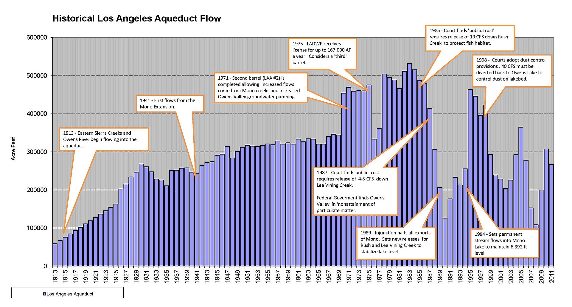
| Los Angeles Aqueduct water flow from 1913 through 2011. Note how imports through the Los Angeles Aqueduct system increased after completion of the Second Aqueduct in 1970 but started to decrease in 1988 after court order restrictions.* |
Historical Notes After the completion of the Second Los Angeles Aqueduct in 1970, water imports to Los Angeles through the aqueduct system increased significantly, reflecting the added capacity and the city's efforts to fully utilize its permitted water rights. However, starting in 1988, court-ordered restrictions aimed at protecting the Owens Valley and Mono Basin ecosystems led to a notable decrease in aqueduct imports, as a substantial portion of the water was redirected for environmental restoration rather than urban supply. |
 |
|
| (2022)* - Water flows down the Original Los Angeles Aqueduct cascade (left) at Sylmar, while the Second Aqueduct cascade (right), with its surge tank and penstock pipe above, remains dry. This contrast highlights the system’s flexibility—when hydroelectric plants are running, most water bypasses the cascades and flows through the penstocks for power generation and reservoir delivery. Photo by Dean Musgrove, Los Angeles Daily News/SCNG). |
Historical Notes In typical operation, the hydroelectric plants handle the full volume of incoming water, so most or all water bypasses the cascades and flows through the penstocks for power generation. This is the most frequent condition, making water flowing down the cascades an occasional event rather than a daily occurrence. The cascades thus serve as an overflow channel, ensuring operational flexibility and system safety during rare periods of maintenance, repairs, or unusually high water flow. |
Water Source Variability (2013–2023)
 |
|
| Over the past decade, the percentages of water Los Angeles receives from the Aqueduct, local groundwater, and MWD have varied significantly year to year. These fluctuations reflect changing precipitation patterns across regions and highlight the flexibility and resilience of a multi-source supply strategy. Source: LADWP |
Historical Notes This 10-year chart shows how Los Angeles relies on a mix of water sources—from the Los Angeles Aqueduct to local groundwater, MWD imports, and recycled water. The amount we get from each source changes from year to year, depending mostly on how much rain and snow falls in each region. In dry years, we depend more on imported water from the Metropolitan Water District. In wetter years, the Los Angeles Aqueduct provides more. Local groundwater plays a smaller but important role, and recycled water stays steady. These changes show why having water from different places is so important. It gives the city flexibility and helps make sure we have a reliable water supply, even when the weather doesn’t cooperate |
* * * * * |
References
* LADWP: Publication - A Second Aqueduct
< Back