Construction of the Los Angeles Aqueduct
Between 1908 and 1913, the City of Los Angeles undertook one of the most ambitious public works projects of its era: the construction of the Los Angeles Aqueduct. Designed under Chief Engineer William Mulholland, the gravity-fed system carried water more than 233 miles from the Owens Valley to a rapidly growing city in Southern California. Built at a cost of approximately $23 million, the aqueduct tapped the Owens River and delivered its flow south, reshaping the city's future. At the time of its completion, it was widely regarded as one of the greatest engineering achievements in the world, rivaled only by the Panama Canal.The images and notes that follow trace how the aqueduct was planned, built, and put into operation, from early surveys and engineering reviews to tunneling, concrete work, power generation, and the challenge of moving men, materials, and machinery across deserts and mountains. Together, they document not only the construction of a water system, but the people and labor behind it, and the moment when Owens Valley water first reached Los Angeles. |
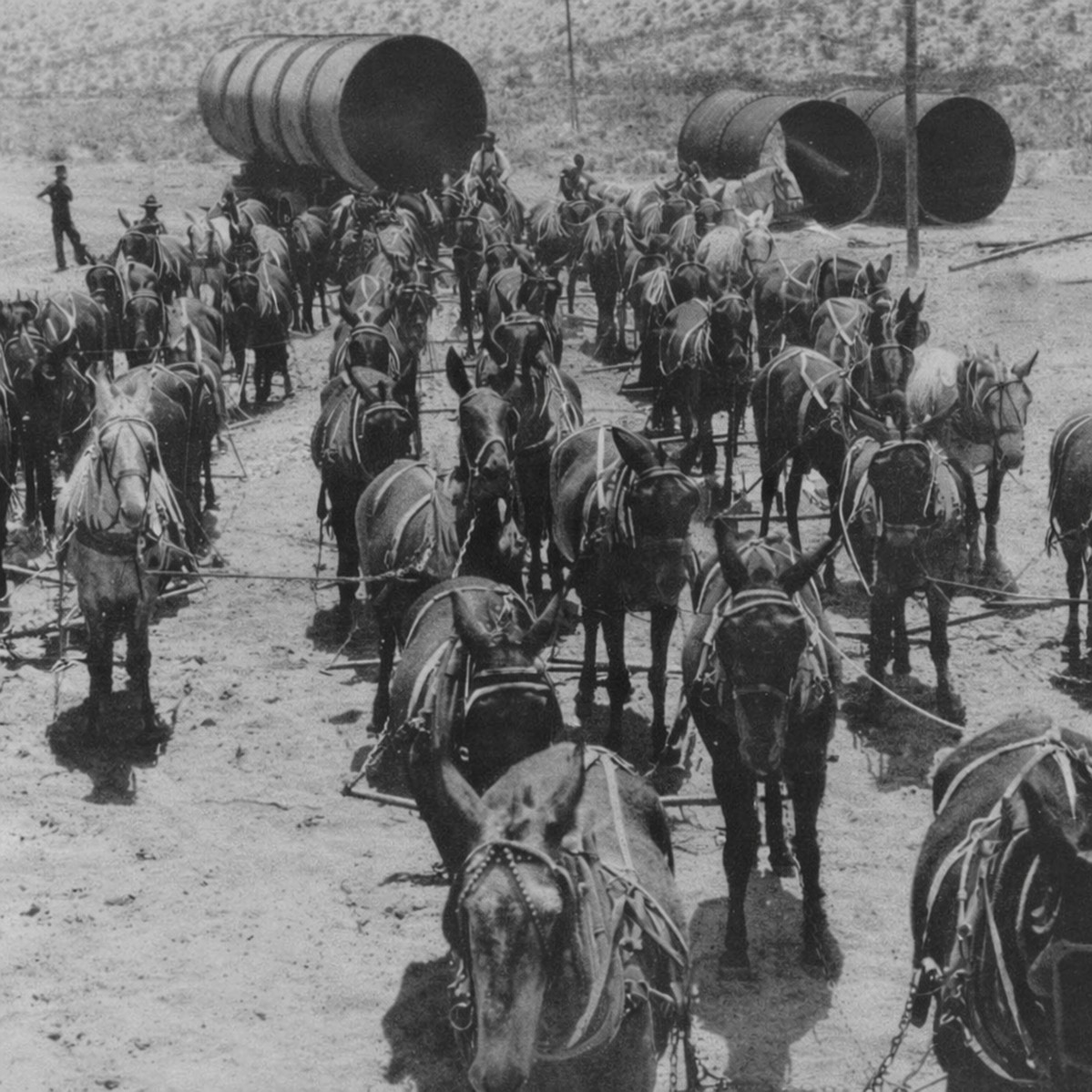 |
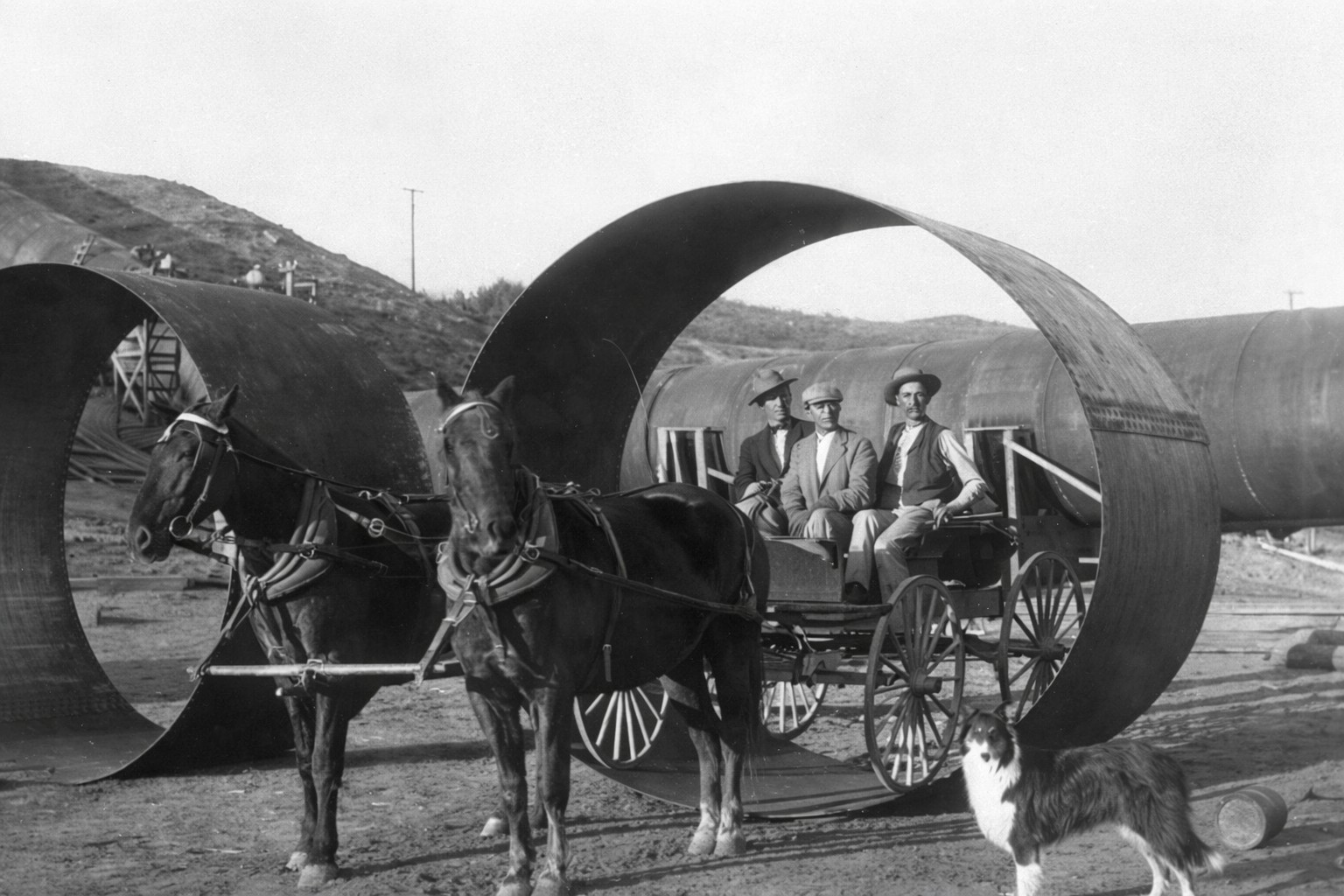
| (1912)* - 52-mule team hauling sections of aqueduct pipe to the Jawbone Siphon. |
|
What's on This Page The construction of the Los Angeles Aqueduct was one of the largest public works projects in American history. This page follows the project from early planning and engineering review through tunneling, camps, power plants, siphons, mule teams, and the 1913 dedication ceremony. Navigate the sections below
|
Historical Background |
The Los Angeles Aqueduct was designed and constructed by the city's water department, then known as the Bureau of Los Angeles Aqueduct, under Chief Engineer William Mulholland. Completed in 1913, the system delivered water more than 233 miles from the Owens River in the eastern Sierra Nevada to the San Fernando Valley through a gravity flow system of open canals, concrete lined channels, tunnels, siphons, and steel pipe without a single pump along the route.The origins of the project reached back to the early 1900s, when Los Angeles was growing faster than its existing water supply could support. The city relied on the Los Angeles River and local groundwater, sources that engineers recognized could not sustain a major metropolitan population. In March 1905, Mulholland reported to the Board of Water Commissioners that the Owens Valley was the only viable long term source. The city moved quickly: federal rights of way were secured in 1906, an independent board of nationally respected engineers reviewed and endorsed the design, and in 1907 Los Angeles voters approved a $23 million bond to fund construction. Actual work began in 1908.The project employed a workforce that reached nearly 3,900 men at its peak, operating across 57 camps spread along the route from Owens Valley to the Tehachapi Mountains and the Mojave Desert. Workers drilled and blasted 142 tunnels totaling more than 43 miles, poured millions of barrels of concrete, and moved steel pipe sections weighing up to 30 tons across terrain that offered no roads and few mechanical alternatives. The city built its own cement plant at Monolith near Tehachapi, constructed two hydroelectric plants in the Owens Valley to power electric dredges and construction equipment, and deployed early caterpillar tractors alongside mule teams that ultimately proved more reliable under harsh desert conditions.The aqueduct was completed ahead of schedule and under budget. On November 5, 1913, more than 30,000 people gathered at the San Fernando Valley cascades near Sylmar to watch Chief Engineer Mulholland open the gates. As water descended the cascade for the first time, he turned to the crowd and said simply: "There it is. Take it."The system has remained in continuous operation ever since. More than a century later, it continues to supply a significant share of Los Angeles' water in an average year, a testament to the engineering standards and construction quality of the original project. |
* * * * * |
Planning, Approval, and the People at the Top |
Before construction could begin, the aqueduct existed only as an ambitious proposal, one that many doubted could be built. City leaders needed to demonstrate that a gravity system spanning deserts and mountains was both feasible and reliable. Funding required voter approval, and respected engineers were brought in to independently review the plans. This section highlights the individuals who shaped the project at its highest level, from the chief engineer who designed it to the advisory board that validated it and the commissioners who guided it through the political process. |
 |
|
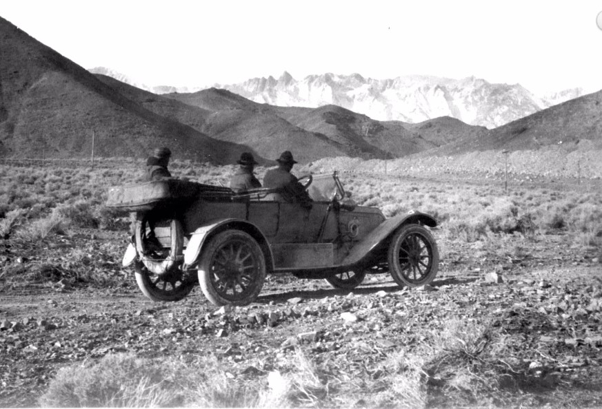
| (ca. 1906)*– William Mulholland and two companions in the Owens Valley, looking toward the snow-covered Sierra Nevada. |
| Historical Notes
In March 1905, William Mulholland reported to the Board of Water Commissioners that the Owens Valley was the only realistic source of additional water for Los Angeles. He had surveyed every available option in Southern California and found the others inadequate for a city growing as fast as Los Angeles was. The following year, the city applied for federal rights-of-way to build an aqueduct, and in 1907 voters approved a $23 million bond to fund construction. Mulholland was a self-taught engineer who had risen from ditch tender to chief engineer of the city's water system through decades of hands-on experience. When he gazed toward the snow-covered Sierra Nevada in photographs like this one, he was not simply admiring the view. He was calculating how gravity could carry that snowmelt all the way to a thirsty city more than 200 miles south. |
 |
|
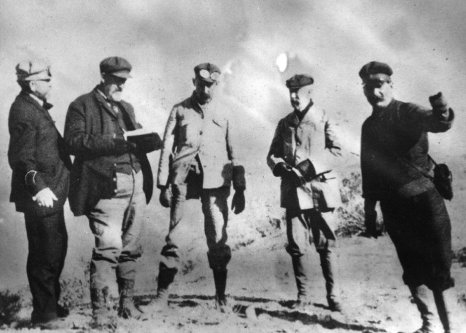
| (1906)* - The independent Board of Engineers appointed to review Mulholland's scheme for the Los Angeles Aqueduct. From left: John R. Freeman, James D. Schuyler, Joseph P. Lippincott, Frederick P. Stearns, and William Mulholland. |
| Historical Notes
With a major bond election approaching, the Los Angeles Water Commissioners appointed an Aqueduct Advisory Board of three nationally recognized civil engineers: John R. Freeman, James D. Schuyler, and Frederick P. Stearns. The board conducted an independent review of the project's design, cost, and feasibility, and released their findings in fall 1906, describing the plan as admirable in conception. Their endorsement helped quiet skeptics and laid the groundwork for strong voter support. The choice of John R. Freeman was particularly strategic. He was one of the most respected hydraulic engineers in the country, with consulting credits on New York's Croton Aqueduct and the Panama Canal. His involvement gave the panel's conclusions a weight that few critics were willing to challenge. After the report was released, serious opposition to the project largely fell silent. |
 |
|
| (1906)* – Advisory engineer James D. Schuyler surveys the terrain along the proposed aqueduct route. |
| Historical Notes
James D. Schuyler was one of the three independent engineers appointed to review the aqueduct proposal. A nationally recognized civil engineer with broad experience in western water systems, Schuyler brought a level of credibility to the review that went beyond any single professional opinion. His presence in the field, shown here surveying the terrain firsthand, signaled that the board was conducting genuine analysis. Schuyler also served on the advisory board for the Panama Canal, giving him direct experience evaluating engineering challenges at an extraordinary scale. His participation alongside Freeman and Stearns helped ensure that when the board declared the project feasible, both the public and the press had reason to take that judgment seriously. |
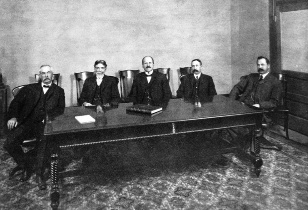 |
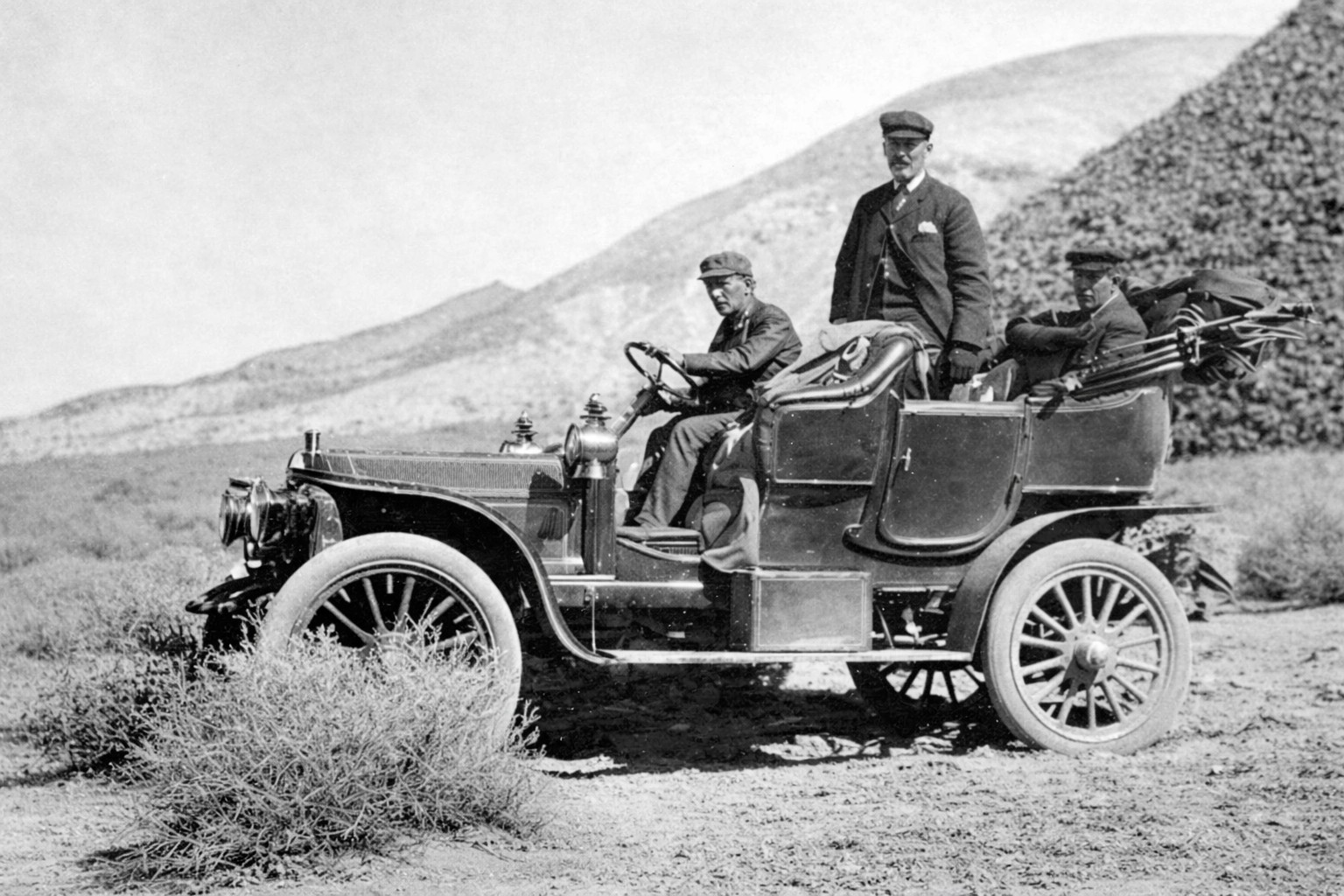
| (ca. 1905)* - The Board of Water Commissioners of the City of Los Angeles. Left to right: John J. Fay, J. M. Elliott, Moses H. Sherman, William Mead, and Fred L. Baker. |
| Historical Notes
The five men shown here were the Board of Water Commissioners at the time the aqueduct was being planned and approved. They held the authority to hire engineers, secure federal rights-of-way, and bring the project before the voters. Without their sustained support, the aqueduct would have remained a proposal rather than a funded construction project. One member, Moses Sherman, has attracted significant historical attention. While serving on the water board, Sherman was also part of a syndicate quietly purchasing land in the San Fernando Valley, which would become the delivery point for aqueduct water. His dual role has never been proven to constitute wrongdoing, but it has remained a persistent source of historical controversy and has long raised questions about who stood to benefit most from the aqueduct's design. |
* * * * * |
Construction Divisions and Leadership |
Constructing the Los Angeles Aqueduct required organization on a military scale. The project was divided into eleven divisions, each overseen by an engineer responsible for a specific portion of the route and type of work — from tunneling through granite in the north to lining canals across the desert floor. This structure allowed construction to proceed simultaneously across dozens of locations, with thousands of workers moving equipment and material across more than 200 miles of remote terrain. The organizational chart and key assignments below show how that effort was structured from top to bottom. |
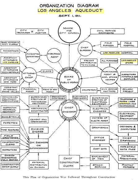 |
The Board of Public Works had charge of the expenditure of all bond moneys derived from the sale of Aqueduct and Power bonds.
William Mulholland was appointed the Chief Engineer.
J.B. Lippincott was appointed Assistant Chief Engineer. |
| (1911)*- Organizational Chart for the Construction of the LA Aqueduct. |
Key construction roles included the following assignments: H. A. Van Norman was in charge of the construction work done with dredges and the building of the unlined canal on the Owens Valley division. O.W. Peterson was in charge of the construction of the open lined canal from the north end of the Alabama Hills to the Haiwee reservoir. Phil Wintz had charge of the building of the South Haiwee Dam. C. H. Richards was in charge of the construction of the covered conduits and tunnels in the Rose Valley and Little Lake divisions. F. J. Mills was Division Engineer of the Grapevine division, consisting of tunnels and pressure pipes. Louis Mesmer built the Freeman Division. A. C. Hansen completely constructed the Jawbone division and a large portion of the Mojave division. John Gray had charge of the greater portion of the construction of the Elizabeth Tunnel and the power tunnels in the San Francisquito Canyon. W. C. Aston was in charge of the south portal of the Elizabeth tunnels and steel pipe. E. F.Scattergood was Electrical Engineer in charge of construction of the power plants. Roderick MacKay had general supervision of the operation of the cement mill and of the selection and advisory of the heavy mechanical equipment. E. W. Bannister was Office Engineer in general charge of the drafting room and of the office of records. |
* * * * * |
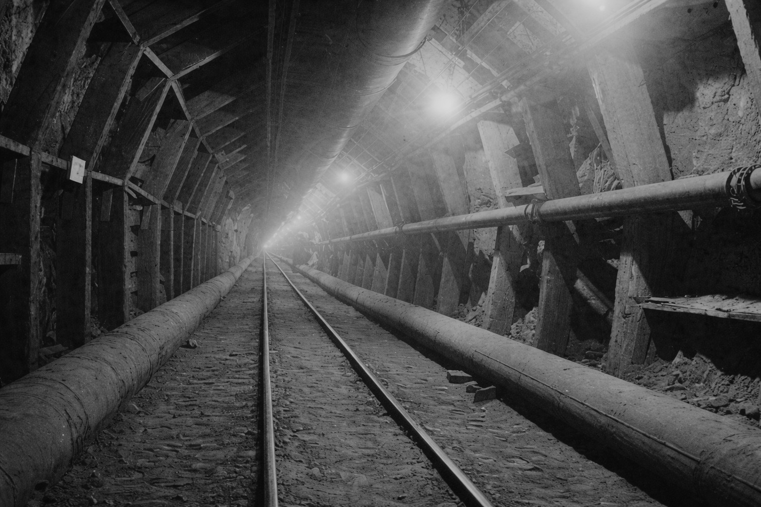
Tunneling: The Hardest Work |
Of all the tasks involved in building the Los Angeles Aqueduct, none was more demanding or more critical than tunneling. Engineers had to drive 142 separate tunnels through mountains and hard rock, totaling more than 43 miles in length, without the aid of modern boring machines. Crews drilled into the rock, packed the face with explosives, cleared the rubble, and repeated the process day after day in heat, dust, and darkness hundreds of feet underground. Ventilation was limited, cave-ins were a constant danger, and flooding could halt progress without warning.The longest and most important of these was the Elizabeth Tunnel, a five-mile passage through solid granite near Elizabeth Lake. Mulholland understood that no water could reach Los Angeles until this tunnel was complete, making it the controlling task of the entire project. Crews worked from both ends at once, driving toward each other through the mountain. When the two headings finally met in February 1911, it marked one of the most celebrated moments of the entire construction effort. |
 |
|
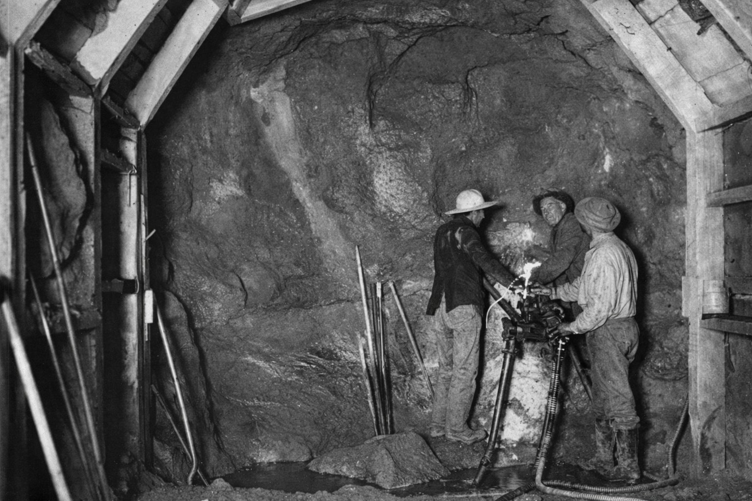
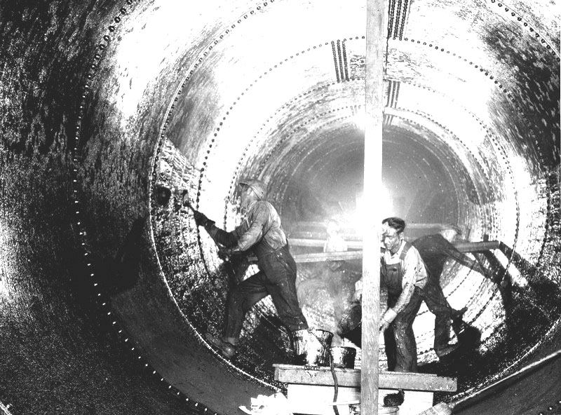
| (ca. 1908)* - Construction crew drilling in the Elizabeth Tunnel. |
| Historical Notes
This photograph captures a crew at work inside the Elizabeth Tunnel during its early stages of construction. The men are using pneumatic drills — equipment that, combined with controlled blasting, allowed crews to advance the tunnel faster than engineers had originally estimated. The workforce included experienced hardrock miners from across the American West and immigrants from communities including Greeks, Bulgarians, Swiss, and Mexicans. A city bonus of 40 cents per man for every foot beyond the daily target pushed progress to an average of 22 feet per day from each end. Over six million pounds of blasting powder were used across all tunnel work on the project, yet underground fatalities numbered only five men, a result of strict safety standards and the use of high-quality German fuse. |
 |
|
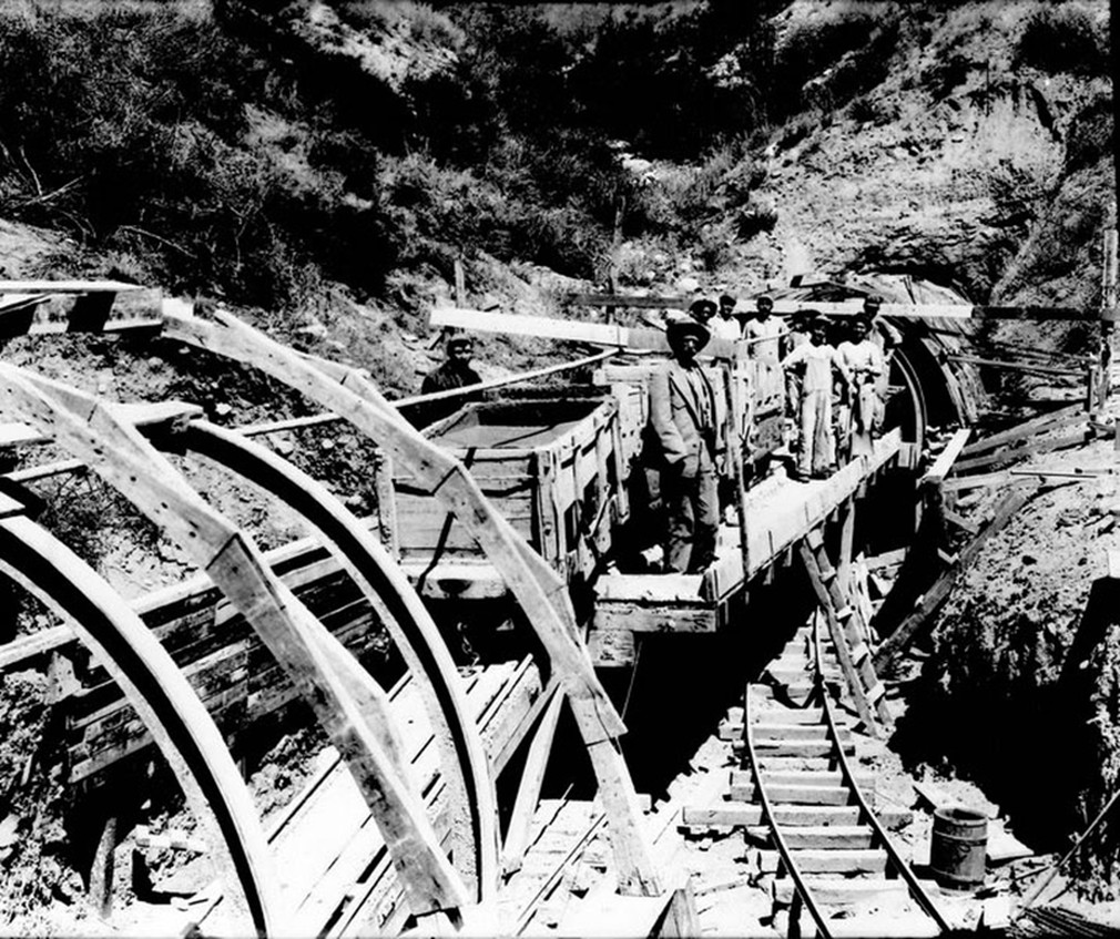
| (ca. 1908)* - Workers preparing a tunnel section for concrete lining. |
| Historical Notes
Once a tunnel section had been excavated, workers built wooden forms shaped to match the curved interior, creating a mold for the concrete lining that would stabilize the walls and seal the channel. The work was done in sections, with forms moved forward as each pour hardened. Lining of the Elizabeth Tunnel began in May 1911, starting at the center and working outward toward both portals simultaneously, with concrete mixing plants operating at each end of the five-mile bore. In areas where the surrounding rock was unstable, steel I-beams replaced the wooden supports and were then encased in concrete, reinforcing the finished structure. The result was a durable, water-tight conduit built to last. |
 |
|
| (1910s)* - Tunnel construction nearing completion. |
| Historical Notes
As work neared its final stages, the focus shifted from blasting and clearing to finishing and inspection. Surveyors verified that each section of tunnel held to the precise grade and alignment established during planning — a demanding standard, given the distances involved and the absence of any direct line of sight between the two portals. The north portal of the Elizabeth Tunnel ran directly through the San Andreas Fault zone, where fractured rock and constant groundwater made conditions particularly difficult. Pumps ran at 350 gallons per minute just to keep the heading passable, and crews often worked in knee-deep water. When a bad flooding episode left the heading submerged to waist depth, superintendent John Gray worked alongside his men for 48 hours before conditions allowed drilling to resume. Moments like that defined what it took to build the aqueduct. |
 |
|
| (1908)* - Men pose in front of the Elizabeth Tunnel at Johnsville, California. |
| Historical Notes
This photograph shows workers at the south portal of the Elizabeth Tunnel, near the construction camp at Johnsville. The south portal was opened in September 1907 and served as the base of operations for one of the two crews that would drive the tunnel from opposite ends over the next several years. On February 26, 1911, the two headings finally met. A miner named Fountain, working from the north end, broke through the last few feet of granite and shouted through the opening. A voice from the south crew answered. Both sides erupted in cheers. The Elizabeth Tunnel was completed roughly 20 months ahead of schedule, and in doing so the crews had set an American record for hard rock tunnel driving — 604 feet in a single month. Their work made the delivery of Owens Valley water to Los Angeles possible. Click HERE to see more in Tunnel Construction on the LA Aqueduct |
* * * * * |
Moving Men and Materials: Tractors and Mule Power |
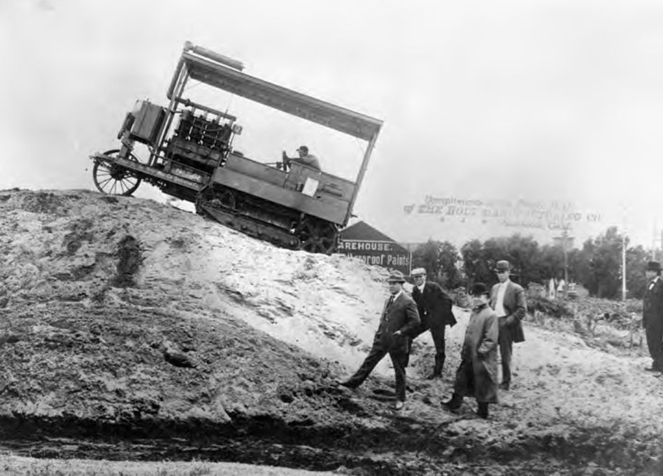
Getting men and materials to remote construction sites was one of the most difficult logistical challenges of the aqueduct project. Much of the route lay far from rail lines, requiring supplies to be hauled across desert and mountain terrain over rough, unpaved ground. Engineers turned to a new technology — the Holt caterpillar tractor — hoping it could replace mule teams and reduce costs. The results would show both the promise of mechanized transport and its limits under harsh desert conditions. |
 |
|
| (1907)* - One of the first Holt Caterpillar tractors used during construction of the Los Angeles Aqueduct. |
| Historical Notes
This photograph captures one of the earliest uses of a caterpillar tractor on the aqueduct project. The machine was sent to the Mojave by the Holt Manufacturing Company of Stockton to demonstrate that tracked equipment could cross the deep sand and steep grades that stopped wheeled vehicles entirely. The tractors used continuous tracks to spread their weight across a broader surface, allowing movement where wheels could not grip. During an early demonstration, William Mulholland reportedly remarked that the machine moved like a caterpillar — a description that became the name still used today. Paul Weston, the Holt representative who delivered the first machine, later recalled that engineers wanted to cut freighting costs that were running as high as 40 to 80 cents per ton-mile using animal teams. |
 |
|
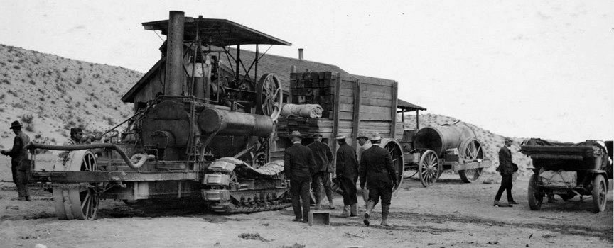
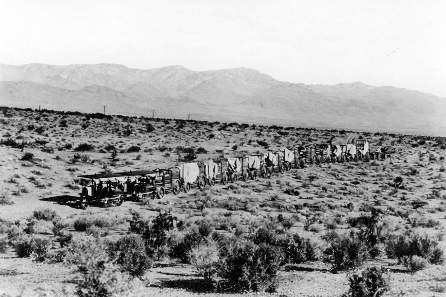
| (1908)* - Caterpillar traction engine hauling lumber in the Mojave Desert. |
| Historical Notes
This scene documents a caterpillar traction engine at work on one of its primary assignments, hauling lumber across open desert to supply construction crews. The machines were expected to handle loads of up to 50 tons across hauls ranging from 4 to 12 miles through sand and over grades as steep as 30 percent. Following early trials, the city placed a large follow-up order, eventually acquiring 25 additional tractors along with 78 specially designed wagons. A report from one section of the project recorded that 14 tractors hauled materials a combined 26,242 miles at an average cost of 20 cents per mile — roughly half the cost of mule teams for the same work. For a time, the advantages of mechanized transport appeared clear. |
 |
|
| (1909)* - Two Holt 45 gas-powered caterpillar tractors pulling a wagon train across the Mojave Desert. |
| Historical Notes
This view shows two Holt 45 tractors working together to move a long wagon train across open desert. By this stage the machines were assigned to the most demanding hauls, including moving 25-ton steam shovels and heavy compressors into areas that could not have been reached any other way without dismantling the equipment entirely. The Holt 45 was a more advanced model than the earlier steam tractors, requiring only a single operator and producing greater power for its size. Performance was encouraging at first, but the desert was placing increasing strain on every moving part, and the mechanical problems were only beginning to surface. |
 |
|
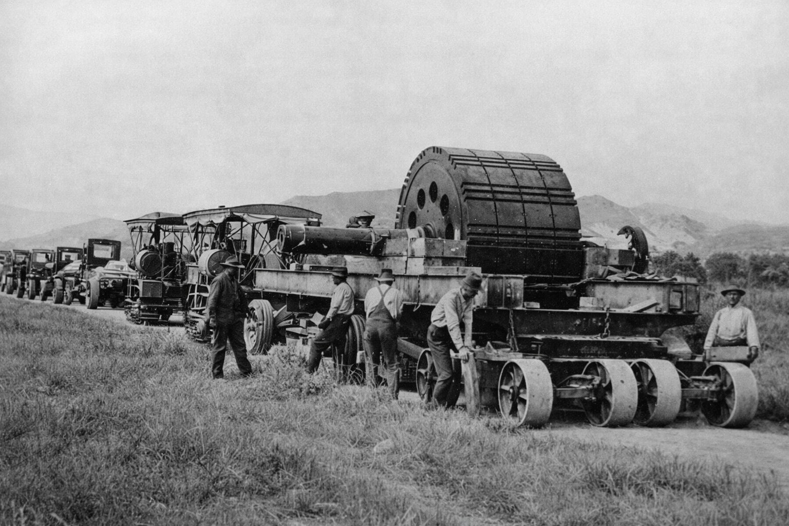
| (ca. 1910)* - Truck fleet and Holt caterpillar traction engine transporting materials to an aqueduct construction site. |
| Historical Notes
By 1910, construction crews were using a combination of early trucks and caterpillar tractors to move supplies. This reflected the project's effort to apply the most advanced available technology to a logistical problem that conventional methods had never fully solved. Conditions in the desert proved harder on machinery than anyone had anticipated. Fine sand and grit worked into every moving part, heat accelerated wear, and spare parts were difficult to obtain in remote locations. As repair costs climbed, the advantages the machines had delivered began to disappear. |
 |
|
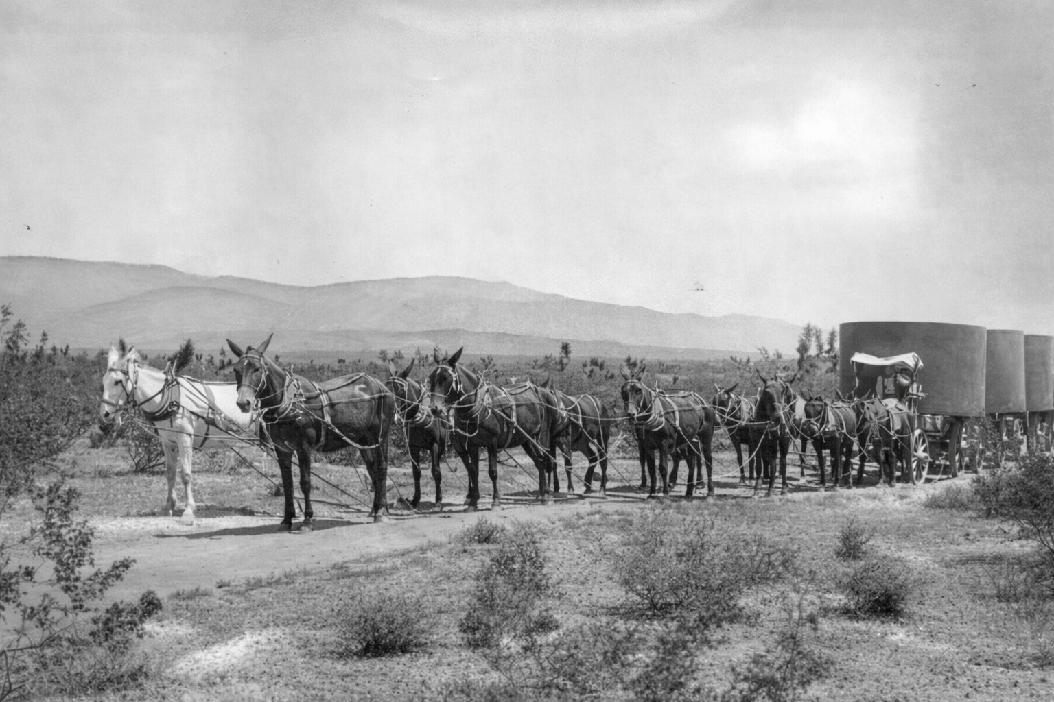
| (ca. 1910)* - Mule team hauling construction materials along the Los Angeles Aqueduct route. |
| Historical Notes
When caterpillar maintenance costs became unsustainable, crews returned to mule teams as the primary means of moving materials. Mules required no spare parts, tolerated extreme heat, and proved far better suited to desert terrain than any machine then available. The city had purchased so many animals that it eventually exhausted the local supply and had to buy mules from the Midwest. The worn-out tractor frames were not wasted — they were repurposed as steel forms for pouring the aqueduct's concrete lining, a practical solution that reflected the project's approach to cost management. In the end, much of the aqueduct was built on animal power, and the mule proved more reliable than the machine age had yet managed to be.
The caterpillar tractor arrived on the aqueduct as a promising new technology and left as a proven one — tested, improved, and better understood because of what the desert had demanded of it. The mules that replaced it finished the job, but the machines that struggled beside them helped shape the future of heavy construction. |
* * * * * |
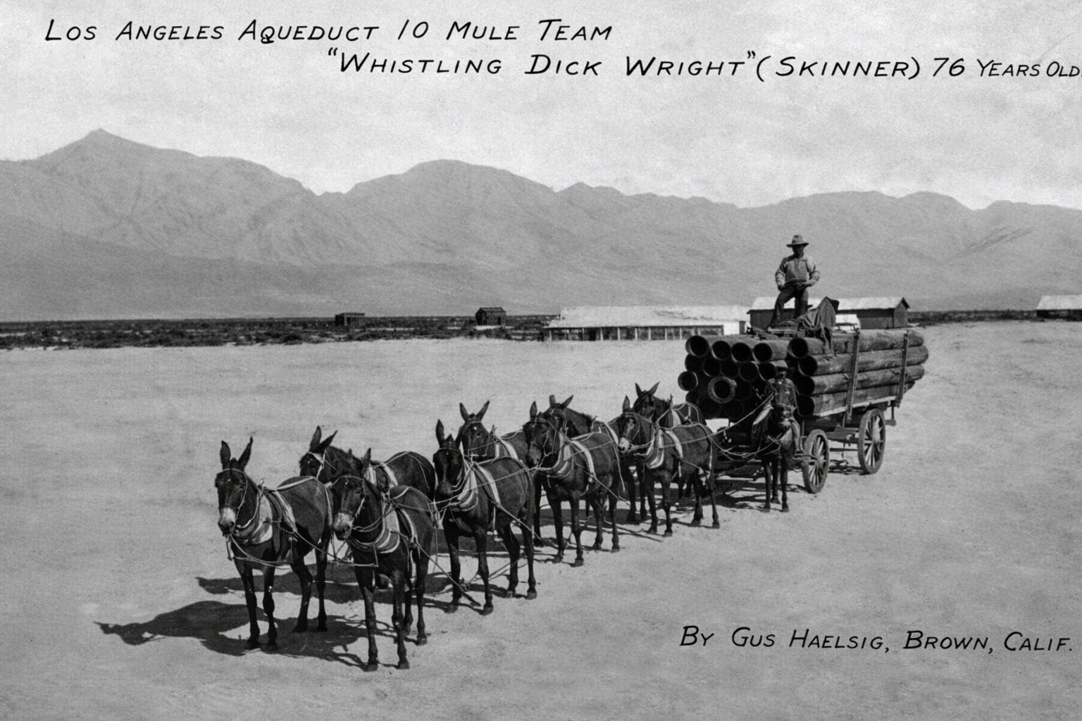
Whistling Dick: Muleskinner of the Aqueduct |
Not all of the individuals who shaped the construction of the Los Angeles Aqueduct were engineers or officials. Some were skilled workers whose experience and reliability made them essential to the project. One of the most notable was a muleskinner known as Whistling Dick, who handled one of the most demanding hauling assignments on the entire route. |
 |
|
| (1912)* - Postcard depicting Whistling Dick and his mule team hauling pipe sections during construction of the Jawbone Siphon. |
| Historical Notes
This postcard is one of the few surviving images associated with Whistling Dick, identified in accounts as Dick Wright. The image was preserved by Ed Fleming, a retired LADWP employee from Mojave, who loaned it for copying in June 1971 and identified Wright as the driver positioned on the left wheel mule, guiding the load with a jerk line, with his two swampers riding atop the pipe. Wright was approximately 74 years old at the time, making him one of the oldest workers on the project. He managed a team of 52 mules, far larger than the standard teams used elsewhere along the aqueduct, to haul pipe sections weighing up to 30 tons across desert terrain where no mechanical transport could operate reliably. According to accounts passed down among aqueduct workers, Wright was hired after claiming he could handle as many mules as he could see, a statement attributed to an encounter with division engineer Harvey Van Norman. Whether exact or not, the record shows that he successfully carried out one of the most difficult hauling operations on the entire project. What is believed to be his grave lies in a small windswept cemetery about one mile southwest of Jawbone Canyon Road, between the routes of the original and Second Los Angeles Aqueducts. |
* * * * * |
Concrete and Cement: Building the Aqueduct |
Concrete formed the backbone of the Los Angeles Aqueduct, lining canals, tunnels, conduits, and structural supports across more than 200 miles of construction. Producing this material in the quantities required posed a major logistical challenge, especially in remote areas far from established supply lines. To ensure a steady and controlled supply, the city took an unusual step for the time — it built its own cement plant. Located near Tehachapi at a site that became known as Monolith, the facility produced most of the cement used on the project and supported a growing industrial community alongside it. |
 |
|
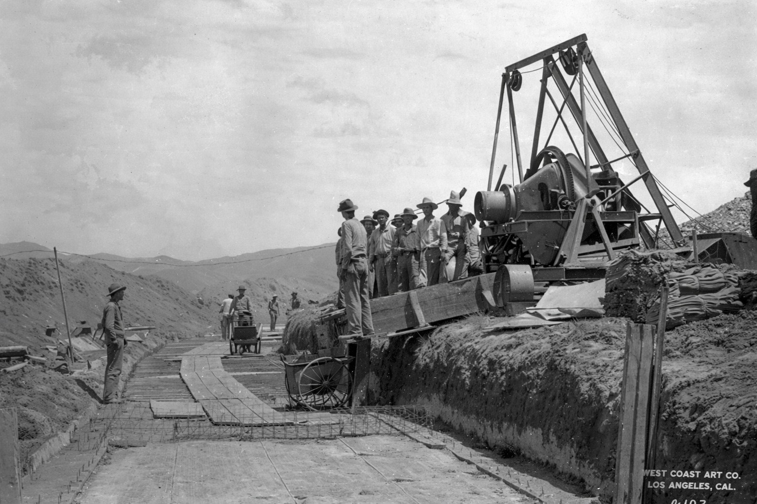
| (ca. 1910)* - Forms being set for concrete lining in an open aqueduct channel. |
| Historical Notes
This photograph shows workers positioning wooden forms that would hold wet concrete in place as it set. These forms shaped the sloped sides of the channel and created a smooth surface that reduced water loss and improved flow. Concrete was used throughout the aqueduct wherever a durable, water-tight lining was required. While steel pipe was considered for some sections, the cost of transporting it from manufacturers in Pennsylvania made concrete the more practical choice for most of the route. |
 |
|
| (1908)* - Workers placing concrete lining in an open channel section. |
| Historical Notes
This image captures the early stages of concrete placement along an open canal. Crews had to coordinate mixing, transport, and placement so that each section could be poured and finished before the material began to set. The scale of this work required a dependable supply of cement at multiple locations simultaneously. Reliance on outside suppliers would have introduced delays and higher costs, leading engineers to develop their own production system. |
 |
|
| (1908)* - On-site mixing plant supplying concrete for aqueduct construction. |
| Historical Notes
Smaller mixing plants like this one were set up near active construction areas to prepare concrete close to where it was needed. This reduced the time and effort required to transport mixed material through remote terrain. Supplying concrete across a project of this length required coordination at every stage, from raw material processing to final placement. The need for consistency and volume led to the development of a centralized production facility at Monolith. |
 |
|
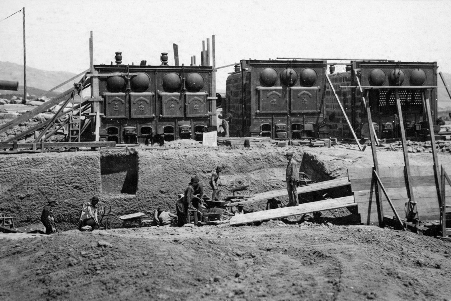
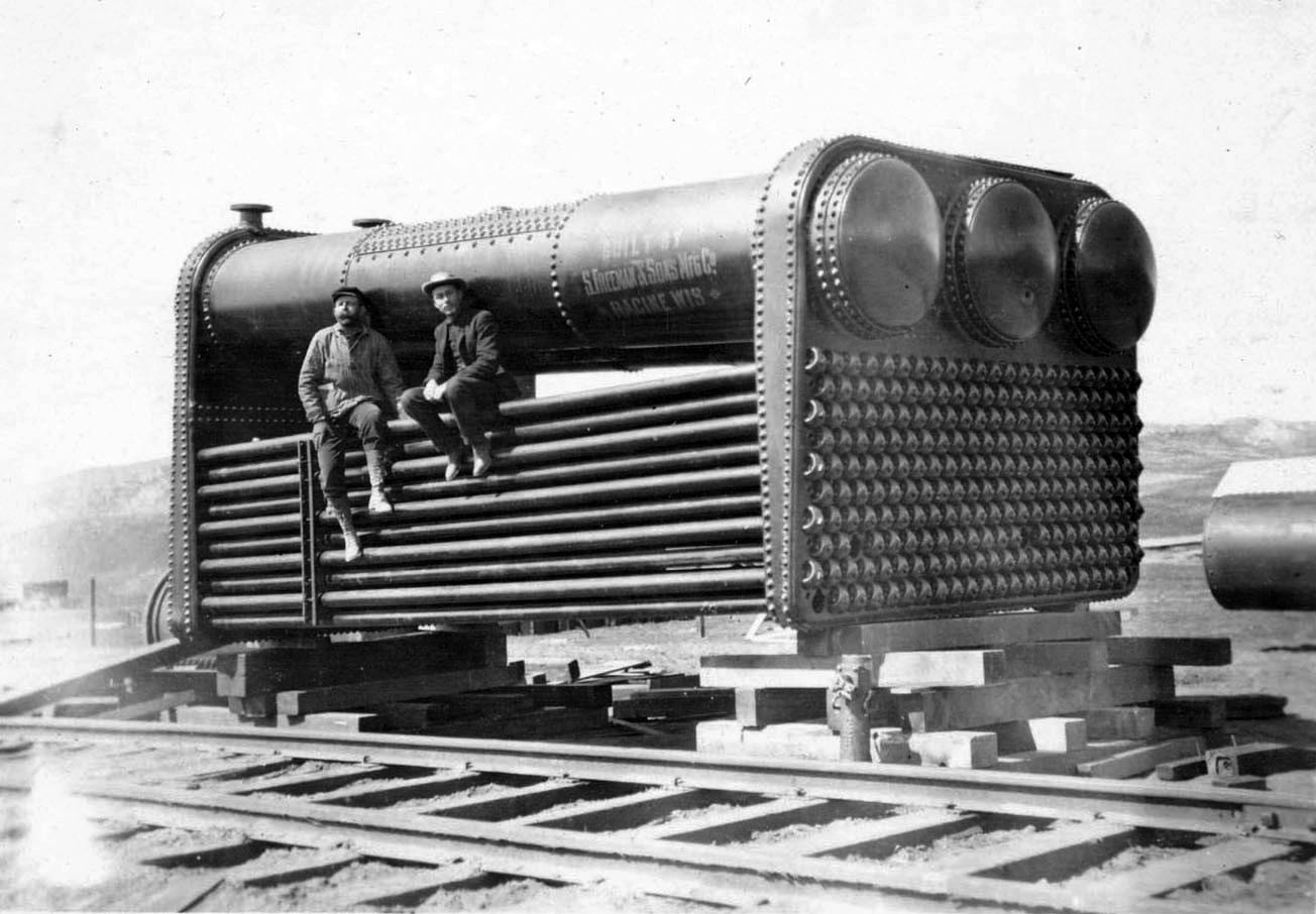
| (ca. 1908)* - Cement mill boilers at an aqueduct construction site. |
| Historical Notes
The machinery shown here was powered by steam, which drove mixers, pumps, and other equipment used in concrete production. At this stage of construction, the hydroelectric plants at Cottonwood and Division Creek had not yet come online, and electrical power was not available along most of the route. Steam plants like this allowed crews to operate independently in remote areas, providing the mechanical power needed to maintain steady production under demanding conditions. |
 |
|
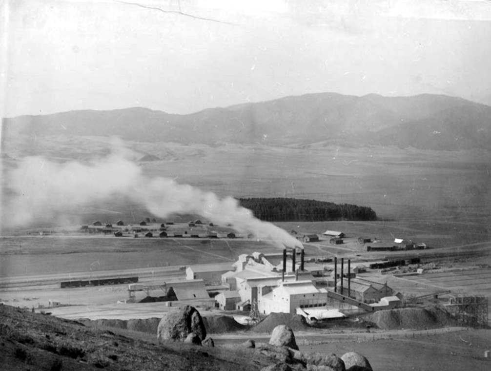
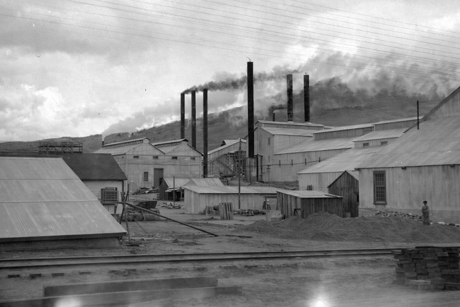
| (1909)* - The Monolith cement plant near Tehachapi, built by the City of Los Angeles to supply the aqueduct. |
| Historical Notes
This image shows the Monolith cement plant shortly after production began in January 1909. The city built the facility after William Mulholland determined that existing mills could not supply the specific tufa cement the project required. The site's location along the Southern Pacific Railroad allowed finished cement to be shipped efficiently toward construction zones. The plant was designed to produce 1,200 barrels of Portland cement per day, drawing on 4,300 acres of land the city purchased to secure limestone quarries, clay deposits, and tufa. Mulholland named the settlement Monolith after the massive limestone deposit on the site, and the post office formally adopted the name in 1910. |
 |
|
| (1909)* - The Monolith plant and surrounding worker community, known originally as Aqueduct City. |
Historical Notes This view shows the plant alongside the community that developed to support it. The city constructed housing, a school, a general store, and service buildings for the approximately 250 workers and their families, creating a self-contained settlement in the Tehachapi Valley. During construction the plant produced roughly 1,200,000 barrels of cement, with 900,000 barrels going directly to the aqueduct. After the project was completed the facility was reorganized for commercial use and continued operating under successive owners well into the twenty-first century. |
 |
|
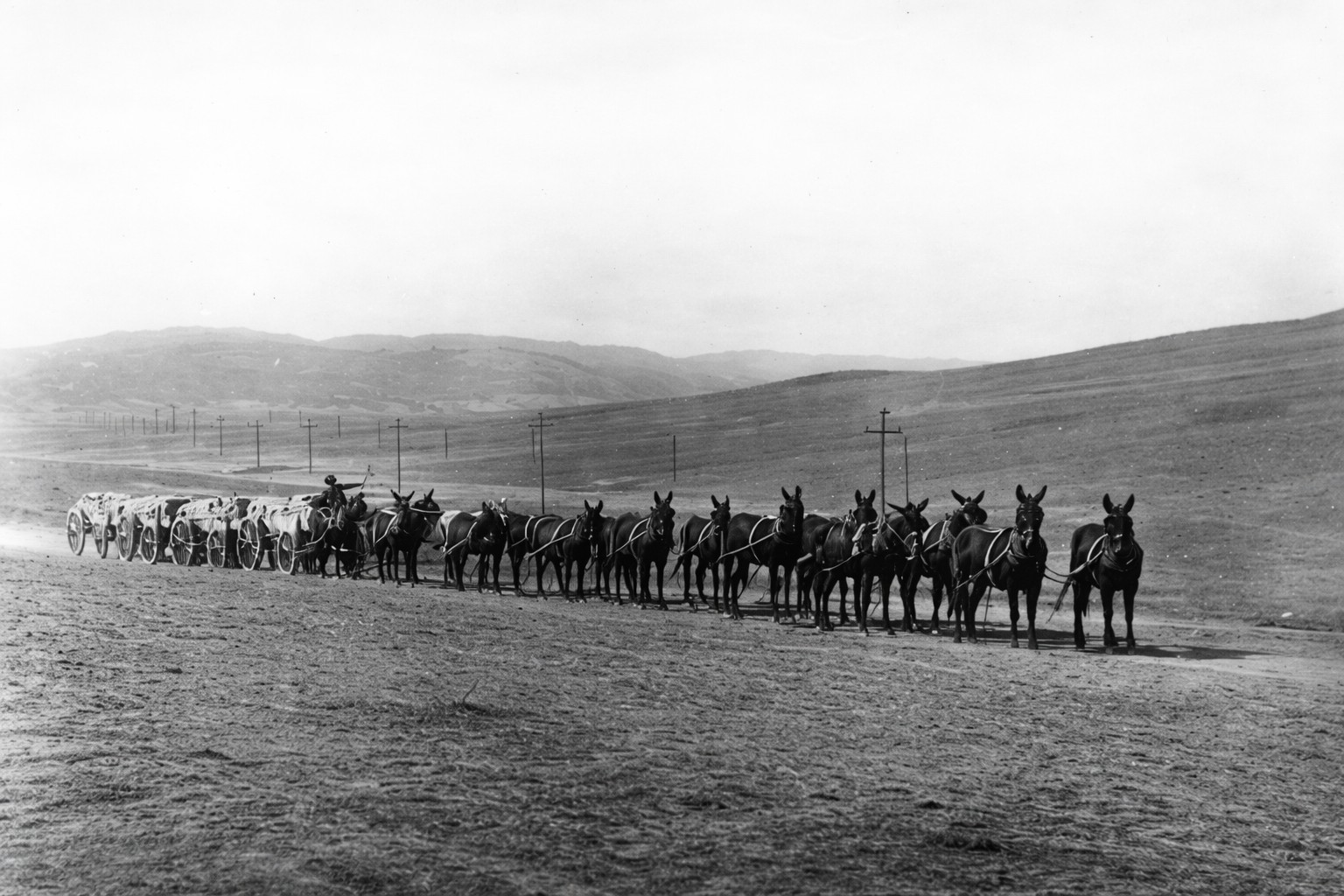
| (ca. 1912)* - A 16-mule team hauling bags of cement from the Monolith plant in the Tehachapi Mountains. |
| Historical Notes
After cement was produced and bagged at the plant, it was shipped by rail to points along the construction route. From there, mule teams carried it over the final distances to active work sites across terrain no vehicle could navigate reliably. This transfer from rail to animal transport was an essential link in the supply chain. Delays at any stage could slow concrete work across multiple sections of the project simultaneously. |
 |
|
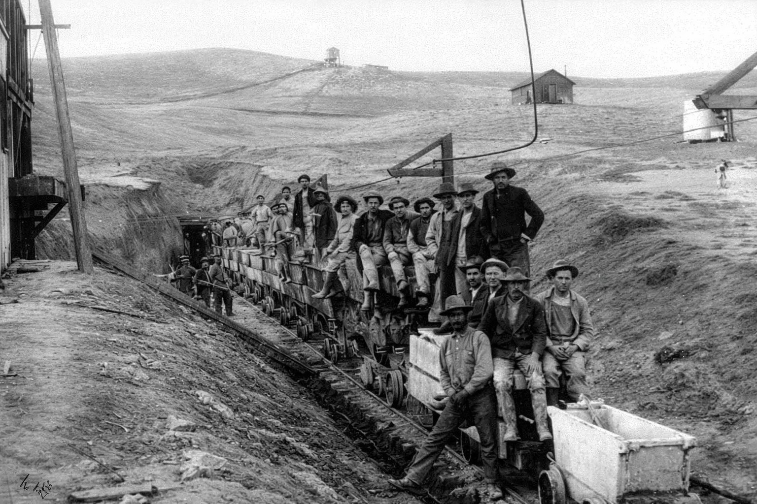
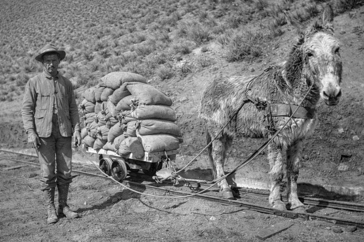
| (1908)* - Worker operating a mule-drawn rail car to transport cement to a construction site. |
| Historical Notes
This photograph shows a narrow-gauge rail system used to move cement and other materials within a construction area. Mule-drawn cars allowed crews to transport heavy loads over short distances along temporary track laid close to the work face. Systems like this bridged the gap between main supply lines and the exact points where materials were needed, reflecting the practical approach to logistics that characterized construction management across the entire route.
The decision to produce cement on-site allowed the aqueduct to be built efficiently across remote terrain. Combined with local mixing operations and flexible transport methods, it ensured that concrete could be placed wherever and whenever the work required it. |
* * * * * |
Camps, Crews, and Daily Life Along the Aqueduct |
Constructing the Los Angeles Aqueduct required thousands of workers to live and operate in remote areas across desert valleys and mountain terrain. At the peak of construction, 57 camps were established along the route, supporting a workforce of nearly 3,900 men. These camps served as the base of operations for field work, providing housing, food service, and logistical support in locations far from established towns. The conditions were demanding, with long hours and extreme temperatures shaping daily life. |
 |
|
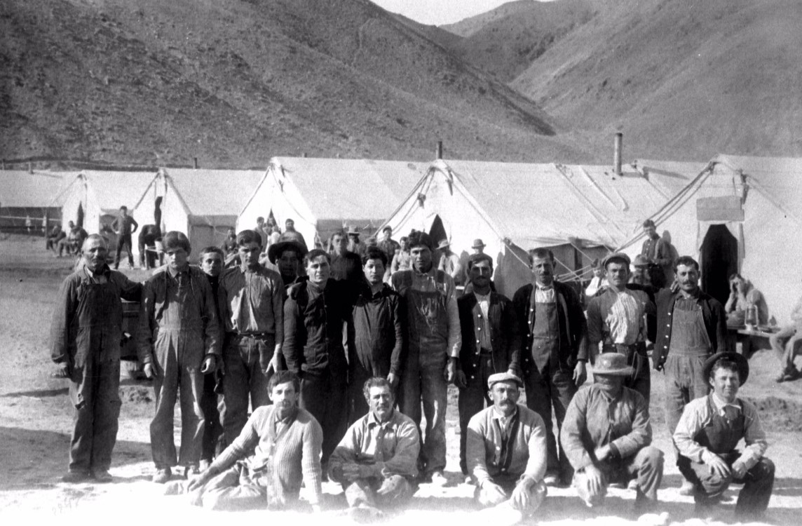
| (ca. 1912)*– Workers posing in front of living quarters at an aqueduct construction camp. |
| Historical Notes
This photograph shows workers at one of the construction camps established along the aqueduct route. Camps typically consisted of wood-frame buildings and canvas tents with raised floors, housing crews assigned to specific sections of the project. Workers lived on site for extended periods, moving as construction advanced. The workforce was diverse and largely transient, with laborers drawn from across the American West and from immigrant communities including Greeks, Bulgarians, Serbs, Montenegrins, Swiss, and Mexicans. Wages averaged about $2.25 per day, while meals cost 25 cents each. Crews worked ten-hour shifts on both day and night rotations, maintaining continuous progress even after California enacted an eight-hour workday law in 1909. |
 |
|
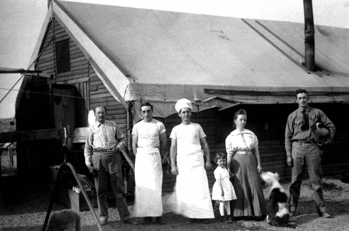
| (ca. 1912)*– Camp cooks and staff outside the mess hall. |
| Historical Notes
This image shows the camp mess hall, where meals were prepared and served to workers on a regular schedule. Feeding large crews in remote areas required a steady supply of provisions delivered by rail and mule team. The quality and quantity of food had a direct effect on morale and productivity. In 1911, dissatisfaction with camp conditions contributed to a general strike among workers at several aqueduct camps — one of the few organized labor actions the project experienced. Archaeological investigation of the Alabama Gates camp, occupied in 1912 and 1913, found that meals included beef, pork, and mutton supplied from outside sources. Camp layouts were organized with dining, sleeping, and work areas positioned to maintain schedules and support efficient operations. |
 |
|
| (1910s)* - Surveying crew during construction of the Los Angeles Aqueduct. |
| Historical Notes
Survey crews were responsible for establishing the grades and alignments that guided all construction along the aqueduct. Working ahead of excavation and building crews, they set the reference points that determined the location of canals, tunnels, and siphons across the full length of the route. The Complete Report on Construction, submitted in 1916, records that the project required 215 miles of road construction, 230 miles of pipeline, 218 miles of power transmission line, and 377 miles of telegraph and telephone line. Survey crews were part of the advance team that made this level of coordination possible across terrain that had rarely been mapped at the precision the aqueduct demanded.
The camps that supported aqueduct construction made it possible to maintain a large workforce across a wide and often isolated landscape. Their organization was essential to sustaining the pace and scale of the project. |
* * * * * |
Powering the Construction: Hydroelectric Plants and Electricity |
Building the Los Angeles Aqueduct required not only labor and materials but a reliable source of power across more than 200 miles of remote terrain. To meet that need, the city constructed two hydroelectric plants specifically for the project — at Cottonwood Creek and Division Creek in the Owens Valley — making it one of the first major construction projects in the country to rely on electricity as a primary power source. That electricity drove the dredges that excavated the unlined canal in Owens Valley and powered the Monolith cement plant in Tehachapi. Where dredges could not reach, Marion steam shovels and mule teams took over across the southern sections of the route. |
 |
|
| (ca. 1908)* - Cottonwood Power Plant, built in 1908 to supply hydroelectric power during construction of the Los Angeles Aqueduct. |
Historical Notes The Cottonwood Power Plant began generating electricity on November 13, 1908, with its first unit producing 900 kilowatts from water diverted from Cottonwood Creek on the west side of the Owens Valley. A second 900-kilowatt unit came online in October 1909, bringing total capacity to 1.8 megawatts. Power traveled over temporary transmission lines to equipment along the route. Cottonwood was one of two plants built specifically to power construction, the other being Division Creek, which came online in 1908 and produced an additional 600 kilowatts. Together they supplied the electric dredges working the unlined canal, construction equipment across the Mojave, and the Monolith cement plant near Tehachapi. Electrical engineer Ezra Scattergood, Mulholland's counterpart on the power side of the project, oversaw their design and construction. His work on these plants laid the foundation for what would become the Los Angeles Department of Water and Power. Click HERE to see more in Electricity on the Aqueduct |
 |
|
| (1908)* - Dredge No. 1 operating on the unlined canal section of the Los Angeles Aqueduct, Owens Valley. |
Historical Notes This photograph shows Dredge No. 1 at work in 1908, drawing power through electric lines connected to the Cottonwood Power Plant. The dredge was the primary excavation tool on the unlined section of the route, cutting through the soft alluvial soil of the valley floor with mechanical efficiency that hand crews could not match. The unlined canal ran 21 miles from the intake across from Aberdeen south to the Alabama Gates, north of Lone Pine. This stretch required no concrete lining because the valley soil held water adequately without it. The electric dredge made it possible to excavate this section rapidly, demonstrating that large-scale electrically driven machinery could function reliably in isolated locations far from established supply lines. |
 |
|
| (1911)* - Dipper dredge working in main canal, Owens Valley. |
| Historical Notes
The dipper dredge shown here uses a hinged bucket mounted on a boom to scoop material from the canal bed and deposit it to the side. This type was suited to heavier or more compacted soils where suction dredges were less effective, and both types were deployed at different points along the unlined section depending on ground conditions. By 1911 dredging operations were well advanced, with crews pushing toward the southern end of the unlined canal. The machines operated around the clock in shifts, taking advantage of the continuous power supply from Cottonwood and Division Creek to maintain progress at all hours. |
 |
|
| (1911)* - Electric-powered dredge working in main canal, Owens Valley. |
| Historical Notes
This view shows a dredge at work in the main canal, with excavated material piled along the bank. Running on electricity gave these machines a clear advantage over steam-driven equipment in remote locations — no fuel deliveries were required and there was no exhaust in the confined canal cut. The decision to build the power plants before dredging began reflected careful planning by the construction team. Without a reliable power source in place, the electric dredge program could not have proceeded on schedule, and coordination between the two was one of the less visible but most consequential organizational achievements of the project. |
 |
|
| (ca. 1910)* - Electric dredge excavating the main canal during construction of the Los Angeles Aqueduct. |
| Historical Notes
The scale of the dredging operation is visible here, with the machine working through material that would have required large hand crews by conventional methods. The electric dredges collectively displaced millions of cubic feet of earth along the unlined section, completing in months work that would otherwise have taken years. The success of this approach was noted by engineers and construction managers across the country, contributing to broader adoption of electrically driven excavation equipment on large public works projects in the years that followed. |
 |
|
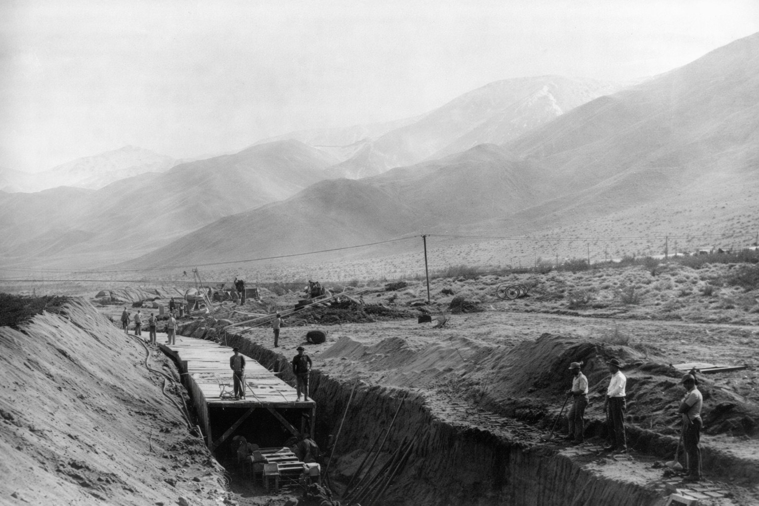
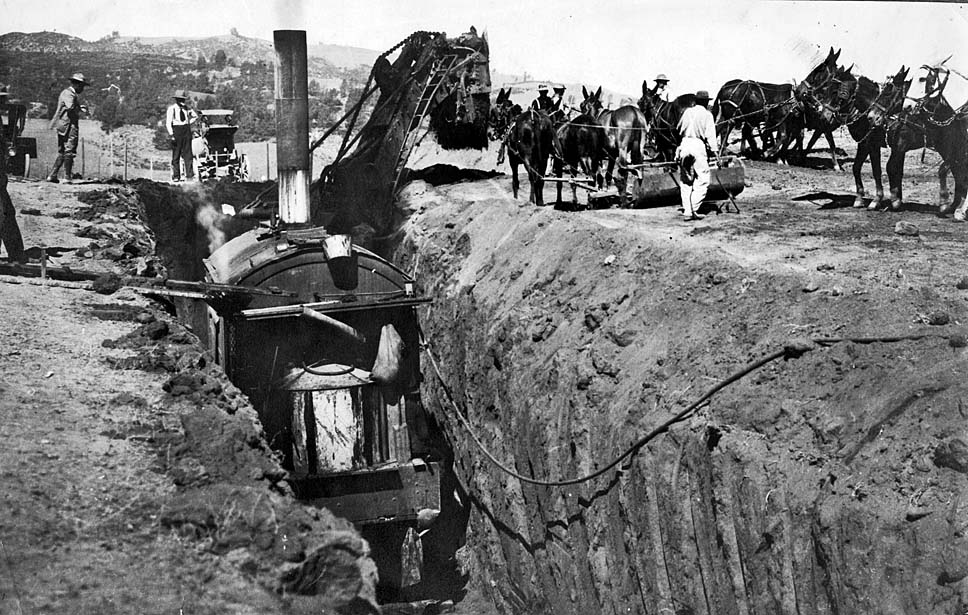
| (ca. 1911)* - Steam shovels and mule teams working together during canal excavation. |
| Historical Notes
Where the unlined canal gave way to concrete-lined sections, steam shovels replaced dredges as the primary excavation tool. They worked alongside mule teams that removed loosened material and transported it away from the work face, with the pace of one system directly determining the pace of the other. This combination of mechanical and animal power was standard across most of the lined canal sections. Steam shovels could break ground efficiently, but moving the excavated material still depended on mules and hand labor — a reminder that even a project powered by electricity was built, in large part, by working animals. |
 |
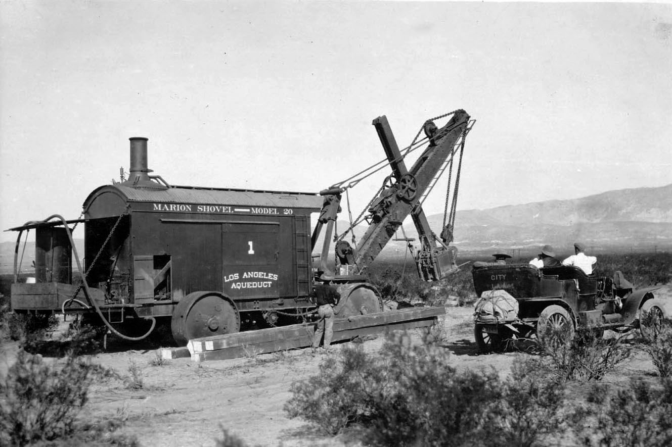
| (ca. 1912)* - Marion steam shovel excavating the open concrete-lined section of the Los Angeles Aqueduct in southern Owens Valley. |
| Historical Notes
The Marion steam shovel shown here was one of the primary excavation machines on the concrete-lined sections. Built by the Marion Steam Shovel Company of Marion, Ohio, these machines were used on major infrastructure projects of the era including the Panama Canal, and their presence on the aqueduct reflected the project's scale and ambition. Powered by wood and coal hauled to remote sites by rail and mule team, the Marion shovels proved more reliable than the caterpillar tractors tested earlier on the project. Their operators worked closely with survey crews to maintain the precise grade profile that concrete forming would require. |
 |
|
| (ca. 1912)* - Steam shovel No. 1 alongside an early automobile at an aqueduct construction site. |
| Historical Notes
The early automobile parked beside steam shovel No. 1 provides an unintentional measure of the machine's scale. By 1912 a small number of vehicles were in use transporting engineers and supervisors between sites, but they remained far outnumbered by mule teams and were unreliable on unpaved desert roads. Steam shovel No. 1 was one of several machines numbered and tracked individually by the construction organization, showing how carefully equipment was managed across the project. Each shovel had its own operator and crew responsible for maintenance and output, with production records kept by division engineers to monitor progress against targets. |
 |
|
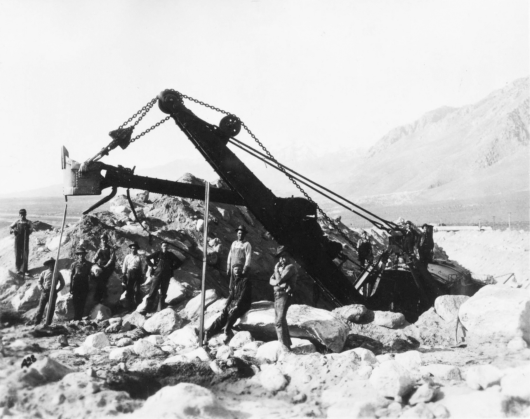
| (ca. 1912)* - Labor crew by steam shovel No. 2 posing for the camera. |
| Historical Notes
The crew shown here — operators, laborers, and support workers — were assigned to steam shovel No. 2, with daily output measured and recorded as part of the project's construction reporting. Photographs like this documented equipment and personnel throughout the project, creating a visual record alongside the official engineering reports. Steam shovel operators were among the better-paid workers on the project, their skill and experience commanding higher wages than general laborers. The crew working alongside them to clear material and maintain equipment formed the larger part of each team, and the two groups working together determined how quickly each section of the canal advanced.
The decision to build dedicated power plants before construction began gave the project a power supply that made electric dredging possible on a scale not previously attempted in American public works. Combined with steam shovel operations across the lined sections, it allowed excavation to proceed simultaneously at dozens of locations and kept the project on schedule through five years of continuous construction. |
* * * * * |
Steel Pipe, Siphons, and High-Pressure Sections |
Where the aqueduct crossed deep canyons and broad desert valleys, neither canals nor tunnels were practical. Engineers turned instead to inverted steel siphons — sealed pipes that carried water down one canyon wall and up the other, using the pressure created by the drop to force it upward without pumps.The aqueduct ultimately included 23 siphons totaling 12 miles of steel pipe, ranging from just over 600 feet to more than 15,500 feet in length and up to 10 feet in diameter. The largest and most demanding of these was the Jawbone Siphon, 8,095 feet of steel pressure pipe crossing a canyon 850 feet deep, about 20 miles north of Mojave. Building it required pipe sections manufactured on the East Coast and hauled four miles across desert terrain by teams of 52 mules — one of the most demanding logistical operations on the entire project. |
 |
|
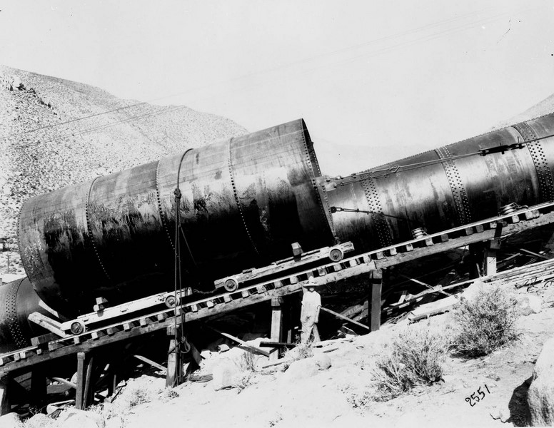
| (1910)* - Construction of the aqueduct pipe in the Mojave Desert. |
| Historical Notes
This photograph shows steel pipe being positioned along the aqueduct route in the Mojave Desert during the early stages of siphon construction. The pipe sections visible here were part of the most technically demanding portion of the project — sections where the aqueduct had to cross terrain that could not be tunneled or channeled and where water pressure would reach levels far beyond anything the open canal sections experienced. Steel pipe for the siphons was manufactured on the East Coast and shipped by rail to staging points along the route. From there, each section had to be moved over rough desert ground using whatever equipment or animal power the terrain would allow. Getting the pipe to the work face without damaging it was a challenge in itself, given the distances involved and the absence of any reliable road across much of the Mojave. |
 |
|
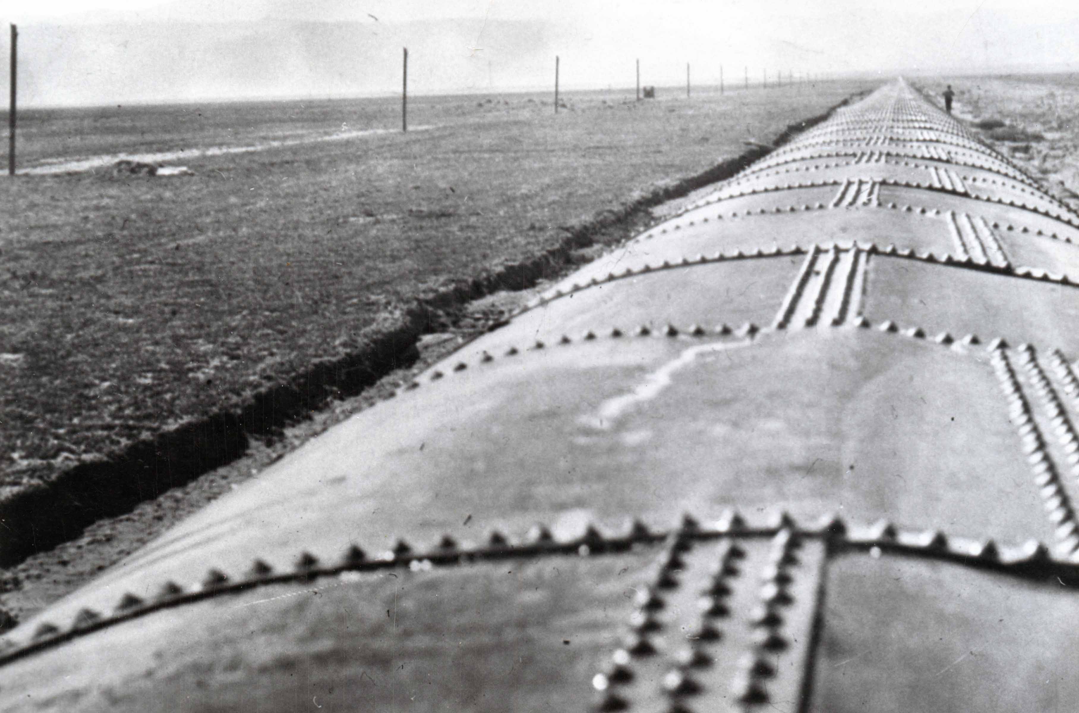
| (ca. 1912)* - Due to the extreme pressure caused by water running down the canyons, the sag pipes needed to be supported by huge concrete pillars. |
| Historical Notes
Where a siphon descended steeply into a canyon and then leveled out at the bottom before rising again, the section at the lowest point — called the sag pipe — experienced the greatest hydraulic pressure of any point on the aqueduct. At Jawbone Canyon, that pressure reached 368 pounds per square inch, requiring steel plate more than an inch thick in the lowest sections. The concrete support pillars visible in this photograph were engineered to hold the pipe firmly against both the weight of the steel and the forces of the water moving through it. The supports and pipe were engineered together as a single structural system. A ten-foot-diameter pipe full of water and under hundreds of pounds of pressure exerts enormous downward and lateral force. Without stable support at regular intervals, the pipe could shift, joints could open, and a failure at the bottom of a canyon would be both dangerous and nearly impossible to reach for repairs. |
 |
|
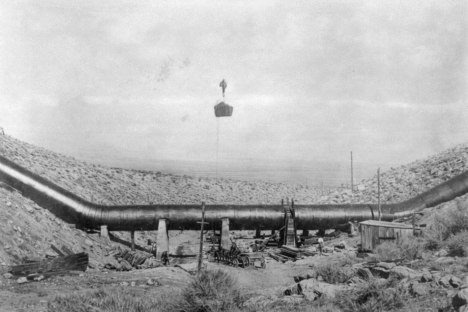
| (ca. 1912)* - View shows one of the methods used for hauling pipe sections up the steep canyons. |
| Historical Notes
Lowering or raising a 25-ton section of steel pipe down a canyon wall required improvised rigging specially designed for the terrain. Crews anchored block-and-tackle systems to rock outcroppings and wooden deadman anchors driven into the canyon rim, using mule teams or hand labor to control the descent. The photograph shows one such arrangement in use, with a pipe section suspended as it is eased down the slope. The Jawbone Canyon installation was described at the time as the most difficult single hauling operation on the entire project. Once sections had been moved four miles from the rail terminus at Cinco to the canyon rim, placing them precisely along the grade profile began — requiring careful survey control and close coordination between the rigging crews and the engineers responsible for alignment. A misplaced section deep in the canyon could not easily be repositioned once set. |
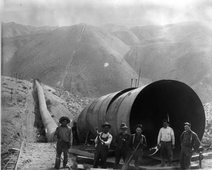
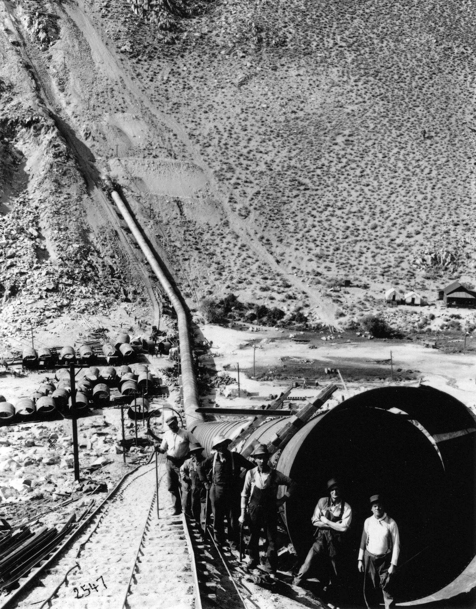 |
| (ca. 1912)* - Workmen posing in front of a new section of the aqueduct pipeline. |
| Historical Notes
The workers shown here are standing in front of a completed section of steel siphon pipe, with the scale of the structure made clear by comparison with the men. Pipe diameters on the aqueduct ranged from 7.5 to 10 feet — large enough, as contemporary accounts noted, to drive a vehicle through. Each 36-foot section was a precision-manufactured product, fabricated to specific wall thicknesses that varied based on the pressure the section would carry. The heaviest sections, destined for the bottoms of the deepest canyons, had walls exceeding one inch of solid steel. The aqueduct's siphon pipe required approximately 191,785 rivets to assemble, varying in diameter from five-eighths of an inch to one and a quarter inches and averaging five pounds each. Riveting crews worked at each joint, driving the fasteners hot and peening them tight before the connection could be tested. The quality of that work determined whether a joint would hold for decades or fail under the first full head of water — a standard the men took seriously, given what a failure deep in a canyon would mean for everyone involved. |
 |
|
| (ca. 1912)* - A team of mules pulling a section of the aqueduct pipeline on a rail. |
| Historical Notes
Once sections of pipe had been hauled by mule team to the general area of a siphon installation, a different system took over for the final positioning. Temporary narrow-gauge rail track was laid along the slope or canyon floor, and sections were loaded onto flatcars or rollers and moved into precise position using much smaller teams — sometimes only two mules for the final placement work. The photograph shows this secondary movement system, which allowed heavy pipe to be shifted the last few hundred feet with a degree of control that rope rigging alone could not provide. The contrast between the 52-mule teams that hauled pipe across the open desert and the 2-mule teams used for final positioning reflects the layered logistics of the siphon work. Each phase of movement required a different approach suited to the terrain and the precision required. The overall system — rail terminus, mule haul, temporary track, final setting — was worked out by trial and adjustment on the project's earlier siphons before it was applied to the more demanding installations at Jawbone. |
 |
|
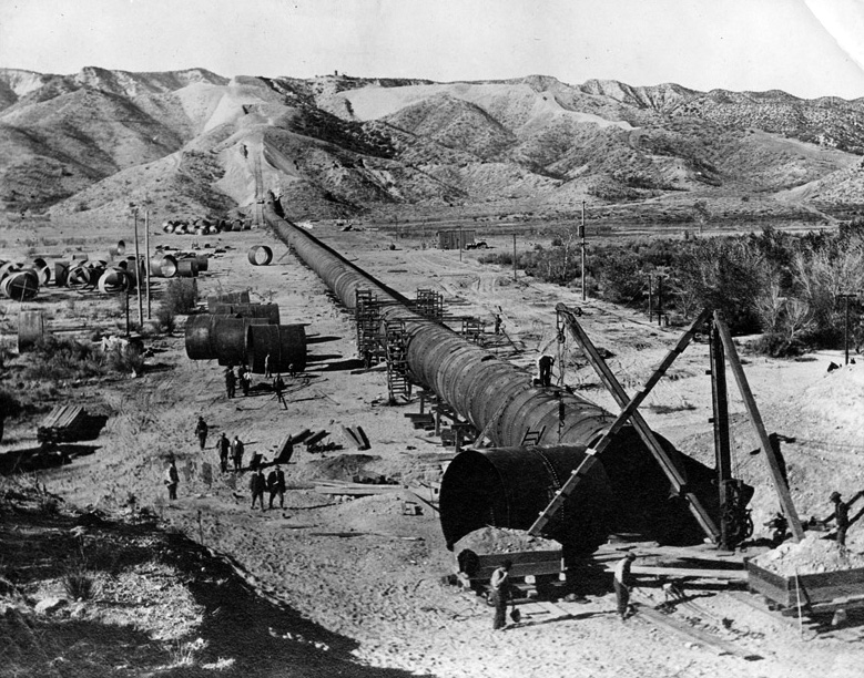
| (1912)* - Construction of the Jawbone Siphon section of the Los Angeles Aqueduct. |
Historical Notes The Jawbone Siphon was the engineering centerpiece of the aqueduct's high-pressure sections. Located approximately 20 miles north of Mojave in a rugged canyon in Kern County, the siphon dropped 850 feet to the canyon floor before rising up the opposite wall — a vertical range that produced pressures no other section of the aqueduct had to withstand. Construction began in January 1912 and proceeded simultaneously from both ends, with pipe sections lowered or hauled into position while rivet crews followed behind to complete each joint. The total weight of steel in the Jawbone Siphon exceeded 3,200 tons, and the pipe varied in diameter from 7.5 feet at the upper ends to 10 feet at the lower sections where flow volumes were greatest. Division engineer A. C. Hansen, who had charge of the Jawbone division, later noted that no single section of the project had required more improvisation in the field. The canyon presented different terrain problems at nearly every bend, and the solutions devised there were applied on other siphon projects across the West for years afterward. |
 |
|
| (1912)* - The Jawbone Siphon begins to take shape. |
Historical Notes This photograph shows the Jawbone Siphon in an intermediate stage of construction, with sections of pipe already set and the system beginning to take its characteristic profile across the canyon. The route followed the natural topography of the canyon walls as closely as the grade would permit, with the pipe supported on concrete saddles and anchored at intervals to prevent movement under the forces it would carry in operation. Engineers considered multiple tunnel alignments and siphon configurations before settling on the final design. The choice to use a single large-diameter steel pipe rather than multiple smaller ones was deliberate — it simplified construction and reduced the number of joints that had to hold under extreme pressure, while making inspection and repair more manageable once the system was in operation. |
 |
|
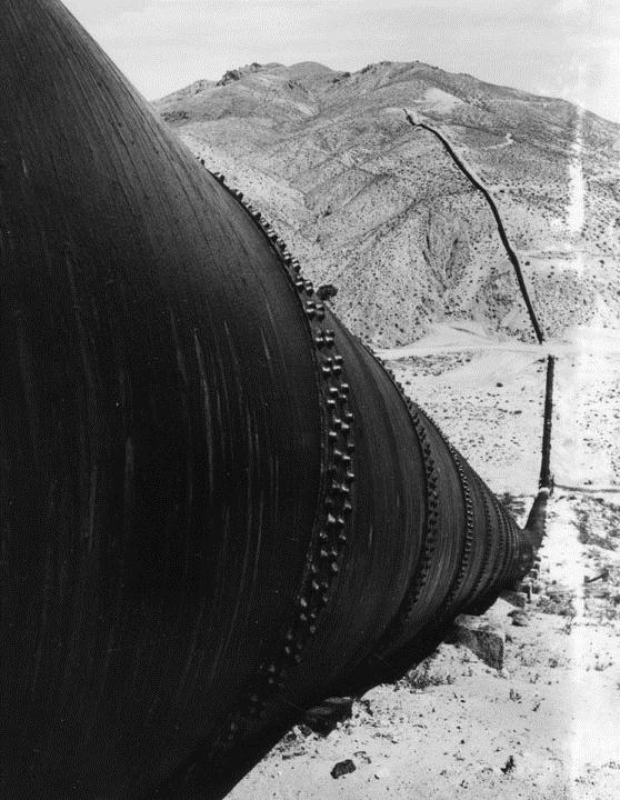
| (1913)* - View showing the Jawbone Siphon from north end. |
| Historical Notes
This view from the north end of the Jawbone Siphon shows the completed pipe descending into the canyon as construction neared its final stages. The pipe descends steeply toward the canyon floor in a continuous curve, following a profile calculated to keep velocity within acceptable limits while allowing the full pressure head to build. Water falling 850 feet to the canyon bottom generates enough hydraulic pressure to force the flow up the southern canyon wall and continue south without any pumping. What was not straightforward was building a structure to contain that pressure reliably across more than a mile and a half of steep terrain, assembled from dozens of separate sections joined in the field by hand. When water was first released in 1913, the siphon held under full operating pressure — confirmation that the rivet crews had done their work well. |
 |
|
| (1913)* - View of the almost completed pipeline in the Jawbone Siphon of the Los Angeles Aqueduct. |
Historical Notes By early 1913 the Jawbone Siphon was nearly complete, with only final joint work and testing remaining before water could be admitted. The photograph shows the siphon at its most complete stage before operation, with the pipe set on its concrete saddles and the canyon work largely finished. Construction had taken just over 14 months, a pace that reflected both the urgency of the overall project schedule and the intensive effort of Hansen's division crew. The Jawbone Division as a whole ran 119,795 feet from Red Rock Summit, at an elevation of 3,320 feet, to the Pinto Hills at 3,171 feet — a total fall of just under 149 feet across more than 22 miles of mixed terrain. Within that distance the division included 60,657 feet of canal, 43,658 feet of tunnel, and 15,480 feet of flumes and siphons. The siphon itself, at the heart of that total, was what made the rest of the division's work possible by bridging the one gap that no other construction method could cross. |
 |
View showing one of the "sag pipes" of the Los Angeles Aqueduct in Jawbone Canyon. The aqueduct is based on gravity flow that does not require pumping or siphoning. Instead, water is conveyed via pressure developed in the down slope to force the water through the up slope. Jawbone Canyon is located just west of Highway 14, south of Randsburg Red Rock Road in Kern County. This section of the aqueduct, built in 1913, was designed by William Mulholland. |
|
| Jawbone Canyon Section of the Los Angeles Aqueduct |
Historical Notes By early 1913 the Jawbone Siphon was nearly complete, with only final joint work and testing remaining before water could be admitted. The photograph shows the siphon at its most complete stage before operation, with the pipe set on its concrete saddles and the canyon work largely finished. Construction had taken just over 14 months, a pace that reflected both the urgency of the overall project schedule and the intensive effort of Hansen's division crew. The Jawbone Division as a whole ran 119,795 feet from Red Rock Summit, at an elevation of 3,320 feet, to the Pinto Hills at 3,171 feet — a total fall of just under 149 feet across more than 22 miles of mixed terrain. Within that distance the division included 60,657 feet of canal, 43,658 feet of tunnel, and 15,480 feet of flumes and siphons. The siphon itself, at the heart of that total, was what made the rest of the division's work possible by bridging the one gap that no other construction method could cross. |
 |
|
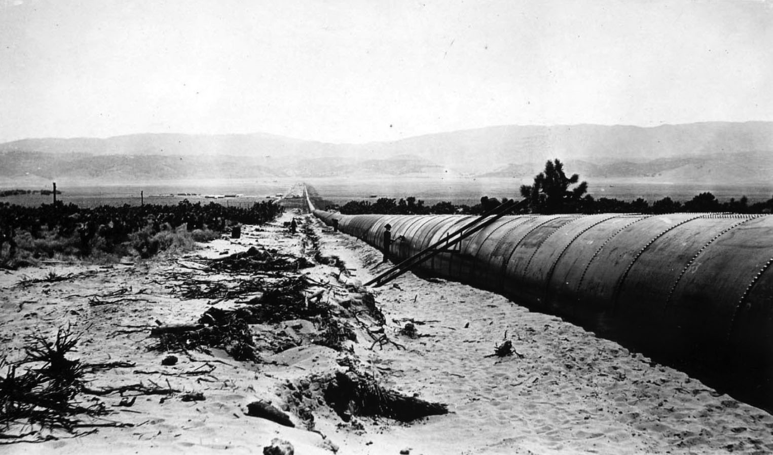
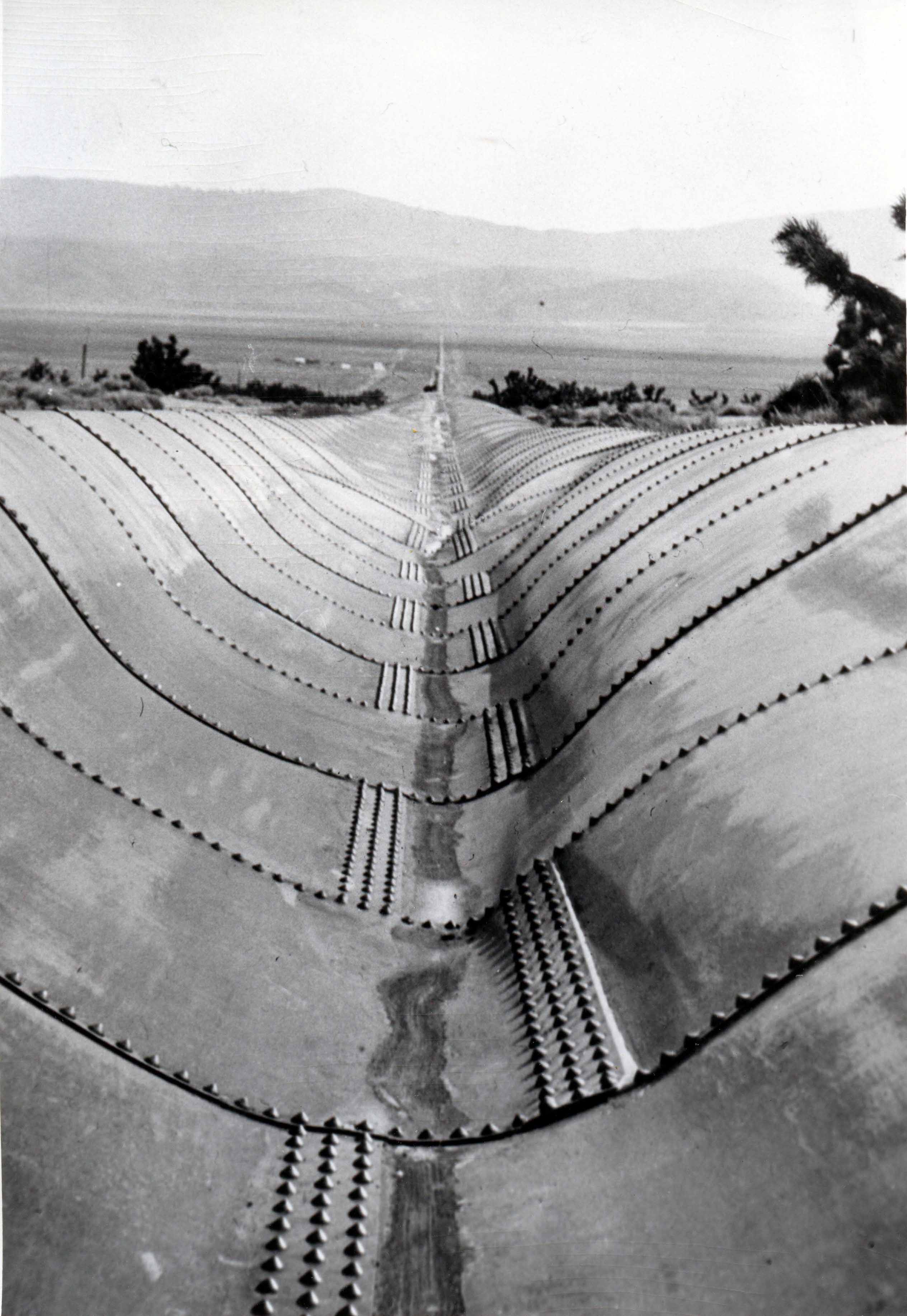
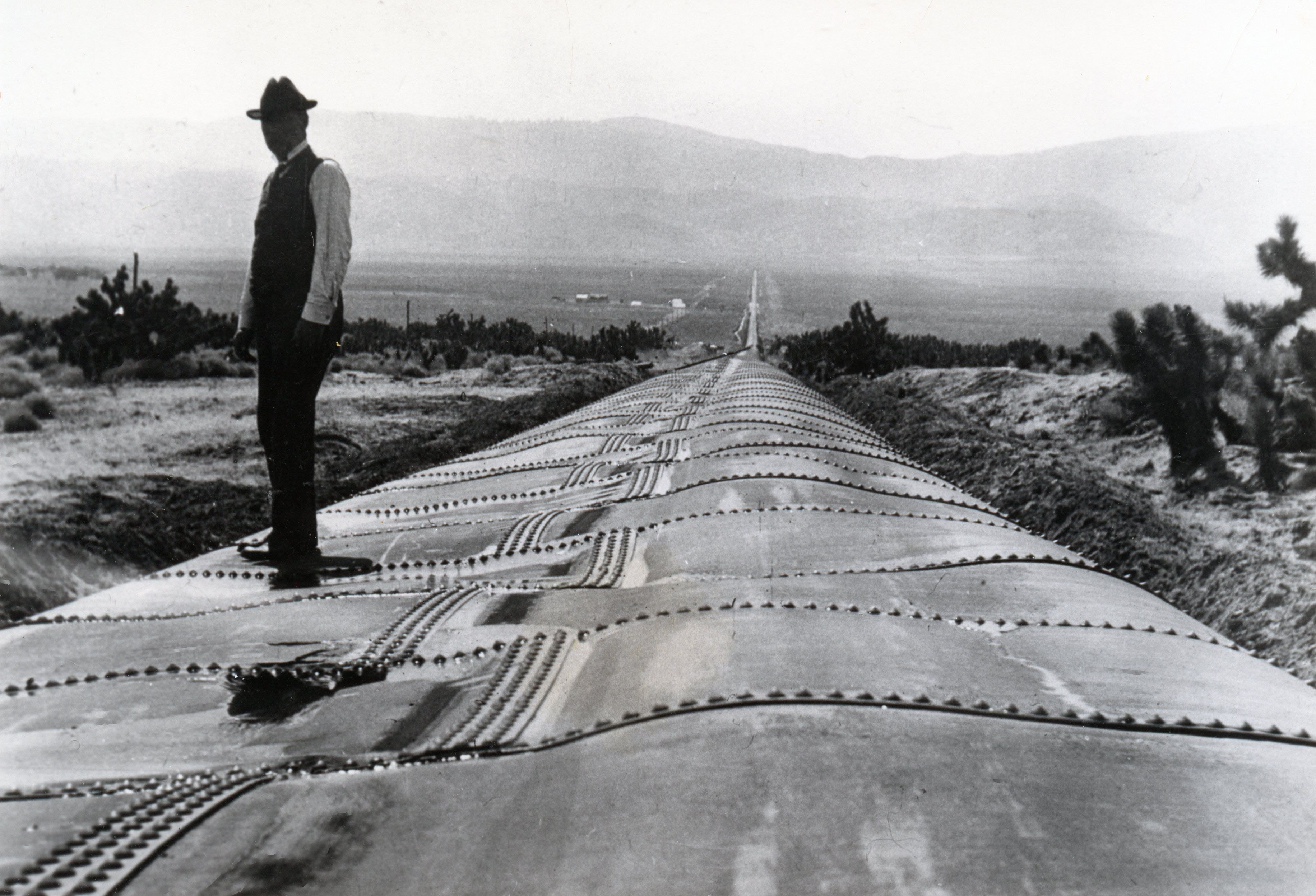
| (ca. 1913)* - View showing the longest section of steel pipe along the aqueduct, running through Antelope Valley. |
Historical Notes The Antelope Valley siphon was the longest of the 23 siphons on the aqueduct, stretching 21,767 feet — more than four miles — across the broad desert valley floor. Unlike the canyon siphons that had to withstand extreme pressure from deep vertical drops, the Antelope Valley crossing presented a different challenge: maintaining flow across flat terrain over a great distance, with a maximum head of only 200 feet. The pipe was 10 feet in diameter and weighed 3,511 tons in steel alone. The upper portion was built in concrete for the first 7,270 feet; the remaining 14,497 feet used steel pipe where higher structural requirements applied. Working on flat terrain 35 miles from the nearest railroad, construction crews had to haul pipe sections across open desert and assemble them without the natural landmarks a canyon provides for survey reference. A 1912 article in Scientific American noted that all of the Antelope Valley siphon work was being done without rail access, making supply and material movement entirely dependent on animal teams. Despite those conditions, the siphon was completed on schedule and became the longest single piece of steel infrastructure on the aqueduct. |
 |
|
| (ca. 1913)* - Close-up view of the longest section of steel pipe along the aqueduct in Antelope Valley. |
| Historical Notes
This close-up view of the Antelope Valley pipe gives a clearer sense of the construction quality and the scale of the individual sections. The 10-foot diameter was standard for the large siphons on the aqueduct, selected to maintain adequate flow velocity while keeping the hydraulic grade within the designed range. Where the terrain was flat and pressure was moderate, as in Antelope Valley, the pipe wall could be somewhat thinner than at Jawbone — but the sheer length of the installation meant that the total steel tonnage exceeded even the Jawbone Siphon. The riveted construction visible here was standard for large-diameter steel pipe in this period. Each joint was a potential point of failure under sustained water pressure, and the workmanship of the riveting crews was one of the factors that determined how long the siphons would remain in service. The Antelope Valley crossing continued to carry water reliably for more than 70 years before replacement sections were installed as part of later system upgrades.
Together, the 23 siphons of the Los Angeles Aqueduct solved the single engineering problem that gravity flow alone could not: crossing the canyons and valleys that interrupted the downhill path from Owens Valley to Los Angeles. From the short canyon crossings in the foothills to the four-mile Antelope Valley traverse and the deep pressure siphon at Jawbone, each installation required custom design, precision fabrication, and labor carried out in remote terrain with minimal mechanical assistance. They were, in the words of one engineering journal of the era, without parallel in American public works. |
* * * * * |
Whitney Siphon |
Most of the siphons on the Los Angeles Aqueduct were built from riveted steel, shipped at great expense from manufacturers on the East Coast. At Whitney Canyon, about 30 miles north of Los Angeles in what is now the Santa Clarita area, engineers took a different approach. The Whitney Siphon was built entirely from reinforced concrete, making it one of the first large concrete siphons on the project and one of the largest concrete pipes of any kind built in the United States up to that time.The decision reflected the lower cost of concrete and the engineers' willingness to test new methods when conditions allowed. Steel for the aqueduct had to be manufactured on the East Coast and shipped around Cape Horn to California, making it one of the most expensive materials on the project. Concrete pipe could be produced for roughly three dollars per foot less than the equivalent steel pipe. Where concrete could do the job, engineers preferred it. |
 |
|
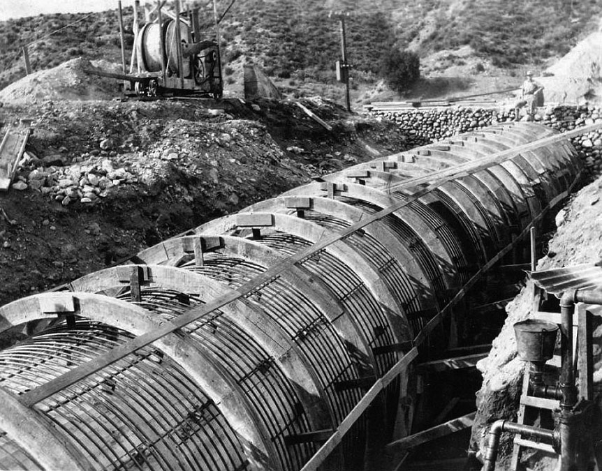
| (1909)* – View showing the Whitney Siphon for the Los Angeles Aqueduct under construction. |
| Historical Notes
This photograph shows the Whitney Siphon under construction in 1909, with the concrete pipe visible as it was being formed in place along the canyon floor. Whitney Canyon carries the aqueduct underground as siphon number 20 on the route, with the adjacent Elsmere Canyon handling siphon number 21. Tunnel 103 connected the two canyon sections. Construction in the area began in 1909, and the Whitney Siphon was among the earliest sections of the aqueduct to be filled with water. The decision to use concrete rather than steel here was largely a matter of cost. Concrete pipe could be produced for roughly three dollars per foot less than the equivalent steel pipe, a significant saving across a siphon of this length. Steel for the aqueduct had to be manufactured on the East Coast and shipped around Cape Horn to California, making it one of the most expensive materials on the project. Where concrete could do the job, engineers preferred it. |
 |
|
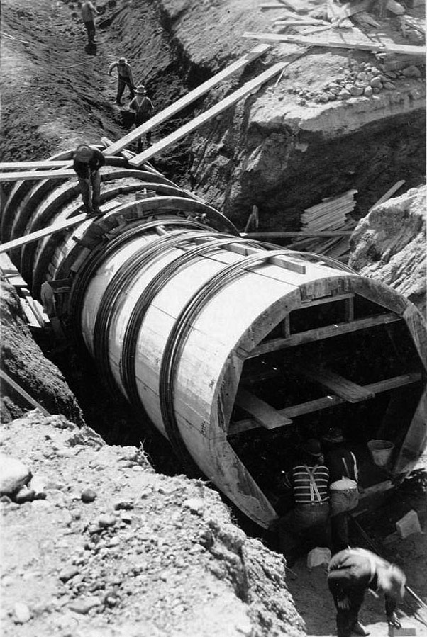
| (1909)* – Close-up view showing construction of the Whitney Siphon, Saugus Division. |
| Historical Notes
This close-up view shows the pipe structure in detail. The Whitney Siphon was a reinforced concrete pipe 10 feet in diameter, cast in place rather than prefabricated and transported to the site. The shell was 8 inches thick on the top and sides, resting on a broad concrete base. Reinforcing steel consisted of half-inch circular iron rods spaced to provide a safety factor of four on the steel alone. Engineers noted in the project's sixth annual report that the concrete mix was made especially rich, and that the concrete itself likely had enough strength to resist the internal water pressure even without the steel reinforcement. When the pipe was first filled with water, leakage occurred at one of two expansion joints built into the siphon to allow for temperature movement. The joints were of the Z type, coated with asphalt paint, and the leakage ran at roughly 4,000 gallons per day. Workers cut out the faulty joints and plugged them with cement. Three months later, leakage had dropped to 320 gallons per day. The Elsmere Siphon, built afterward using the lessons learned at Whitney, was constructed without expansion joints entirely. Together, the two concrete siphons demonstrated that large reinforced concrete pipe could be used successfully in the aqueduct system, and the approach was carried forward on later sections of the project. |
* * * * * |
Transport to Jawbone |
Getting the steel pipe to Jawbone Canyon was a logistical problem unlike anything else on the aqueduct. The pipe was manufactured on the East Coast, shipped by rail across the country, and delivered to a small supply camp called Cinco in the Mojave Desert, about 20 miles north of Mojave. From Cinco, there were no roads suitable for heavy wheeled vehicles. The final four miles to the canyon had to be covered the only way the terrain allowed — by mule.The solution was the 52-mule team, one of the largest working animal configurations ever assembled for a construction project in the American West. Each team hauled a pair of heavily reinforced flatbed wagons fitted with steel wheels and two-foot-wide tires to distribute the load across the desert surface. Three parallel jerk lines controlled the teams, with a lead pair at the front and wheel mules at the wagon tongue. Together, they moved pipe sections that no machine of the era could have carried across that ground. |
|
| (1912)* - 52-mule team hauling sections of aqueduct pipe to the Jawbone Siphon. |
Historical Notes This photograph shows one of the 52-mule teams at work on the desert haul between Cinco and Jawbone Canyon. The pipe sections loaded on the wagons behind them were 36 feet long and weighed approximately 30 tons each. The teams moved these loads across four miles of open desert where no mechanical transport could operate reliably, and where a breakdown meant the entire operation stopped until the problem was resolved. The town of Cinco was established specifically as the staging point for Jawbone construction, serving as the rail terminus where pipe arrived from the East and was transferred to wagon transport. From that point forward, the mule teams took over entirely. The work continued through the desert heat of 1912, with teams making multiple hauls as sections were delivered and the siphon installation advanced down into the canyon. |
| (1912)* - A 52-mule team, six abreast at the wheel, transporting a 30-ton section of steel pipe during construction of the Jawbone Siphon. |
Historical Notes This photograph shows the wagon configuration in detail, with the wheel mules visible six abreast at the rear of the team where the pull was most direct. The wheelers carried the heaviest share of the load stress and required the most experience to manage. The driver controlled the entire team using the jerk line system — a long rope running forward through rings to the lead mules, with signals communicated by a series of steady pulls and jerks that the animals learned to read precisely. The men who drove these teams were among the most skilled workers on the project. A freighter managing 52 mules had to anticipate how the team would move on turns, how the load would shift on uneven ground, and how to keep all the animals pulling together under conditions that tested both the equipment and the animals. Two swampers rode atop the pipe to assist with the operation. Most of the 15,000 tons of siphon steel used across the entire aqueduct was moved this way, by teams like this one, driven by freighters whose skill made the whole operation possible. |
| (1912)* - 52-mule team hauling pipe for the Jawbone section of the Los Angeles Aqueduct in the Mojave Desert. |
Historical Notes This image captures the full scale of the desert haul, with the team stretched out across open terrain as it moves toward the canyon. Photographs like this one circulated widely at the time, and the 52-mule teams became one of the most recognized images associated with the aqueduct's construction. They appeared in newspapers, engineering journals, and promotional materials as a symbol of what the project had demanded of the people who built it. The haul to Jawbone Canyon was the most difficult hauling operation of the entire project. On this section, the combination of pipe weight, desert heat, and the precision required to navigate the canyon approach made it unlike anything else along the route. When the last pipe section reached the canyon and the siphon was complete, the mule teams that had carried it there had moved more than 3,200 tons of steel across ground that offered no other way through. |
* * * * * |
Scale & Completed Pipe |
Photographs in this group emphasize the immense size of the aqueduct’s steel siphon pipe. By placing automobiles, wagons, and people beside or inside the completed sections, the images helped the public understand the scale of the engineering work in a direct and visual way. |
 |
|
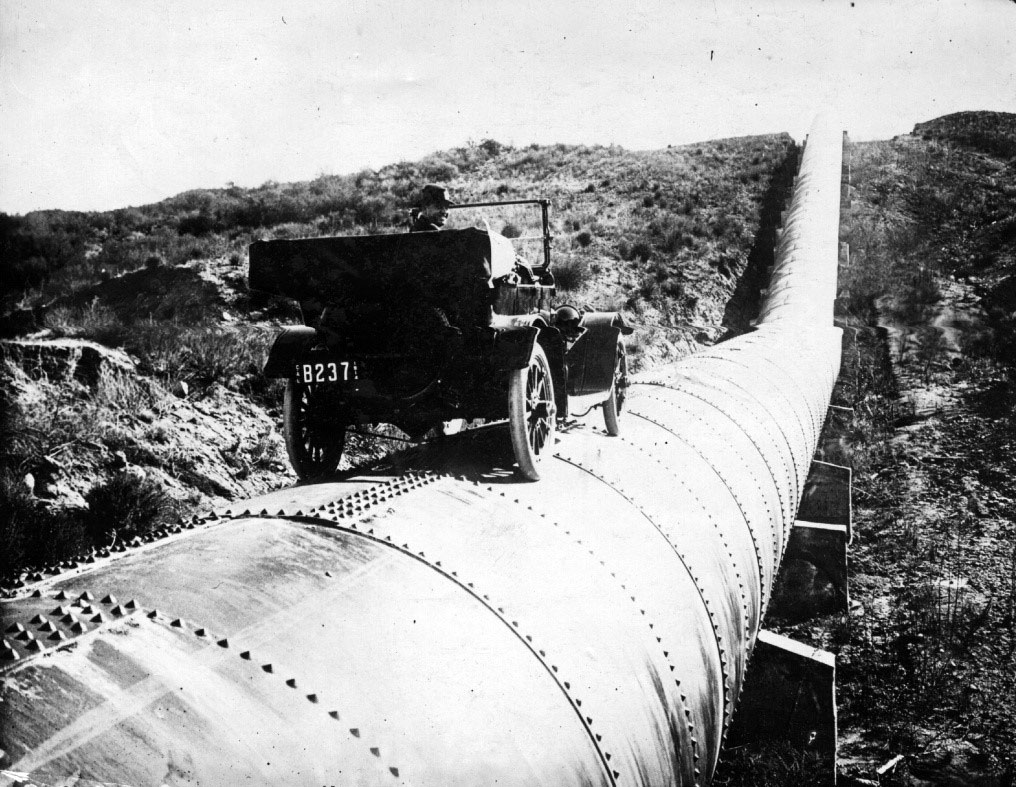
| (ca. 1913)* - Early automobile atop a completed section of Los Angeles Aqueduct siphon pipe. |
| Historical Notes
This photograph uses an early automobile to demonstrate the scale of the completed siphon pipe. The aqueduct’s largest steel sections measured up to 10 feet in diameter, large enough that vehicles and people were often used for comparison in official photographs. By 1913 automobiles were still relatively uncommon on large construction projects, where mule teams remained the primary means of transportation. The image unintentionally captures a transition between two eras — modern motor vehicles appearing alongside infrastructure built largely through animal labor and hand work. |
 |
|
| (ca. 1913)* - Early automobile inside a section of Los Angeles Aqueduct siphon pipe. |
Historical Notes This image clearly shows the immense interior size of the aqueduct’s siphon pipe. The automobile fits comfortably within the opening, helping convey the dimensions of a structure designed to carry enormous volumes of water across canyons and desert valleys under pressure. Photographs like this circulated widely during and after construction, appearing in newspapers, postcards, and engineering publications. They gave the public a simple visual reference for understanding the scale of a project widely regarded as one of the greatest engineering achievements in the American West. |
 |
|
| (n.d.)* - Horse-drawn wagon and workers positioned inside a section of Los Angeles Aqueduct siphon pipe for scale. |
| Historical Notes
This staged photograph uses a horse-drawn wagon and several workers to demonstrate the interior dimensions of the completed siphon pipe. The comparison made the scale immediately understandable to viewers at a time when most people had never encountered infrastructure of this size. The aqueduct’s steel siphons ranged from 7.5 to 10 feet in diameter depending on location and pressure requirements. The largest sections used thick steel plate and thousands of rivets at each connection to withstand the tremendous hydraulic pressure generated in the canyon crossings. When water first flowed through the completed system in 1913, the siphons performed as designed under full operating pressure. |
* * * * * |
Fabrication & Preparation |
Before installation, aqueduct siphon pipe sections had to be carefully fabricated, aligned, and riveted by hand. The work required precision at every stage, since the finished pipe would later operate under tremendous internal pressure across canyon crossings and desert valleys. Riveting crews worked in coordinated teams to create joints strong enough to remain water tight under full operating conditions. |
 |
|
| (1910s)* - Workers preparing Los Angeles Aqueduct siphon pipe sections for riveting. |
Historical Notes The steel pipe sections used in the aqueduct's siphons were manufactured to precise specifications, with wall thickness varying according to the hydraulic pressure each section would carry in operation. The heaviest sections, intended for the lowest points of the canyon crossings, used steel plate more than one inch thick. Once delivered to the work site, the sections were aligned and joined together with rows of heated rivets driven through pre-drilled holes. The aqueduct required approximately 191,785 rivets ranging from 5/8 inch to 1-1/4 inches in diameter and averaging about five pounds each. Riveting crews typically worked in teams, with one man heating the rivet, another positioning it, and a third driving it tight before the metal cooled and contracted. The quality of each connection was critical, since repairs on completed siphons deep within the canyon crossings would have been extremely difficult once the aqueduct entered operation. |
* * * * * |
Storm Damage |
Shortly after the aqueduct opened, a severe 1914 storm in Antelope Valley heavily damaged part of the system's longest steel siphon, providing an unexpected test of the pipeline's design and durability. |
 |
|
| (1914)* - Flood damage to the Antelope Valley siphon following a major three-day storm in February 1914, three months after the aqueduct's opening. |
Historical Notes In February 1914, three days of rainfall in the Mojave Desert region produced nearly 50 percent more precipitation than the area typically received in an entire year. The Antelope Valley siphon crossed a normally dry wash on concrete piers placed outside what engineers believed to be the maximum flood channel, estimated at approximately 15 feet wide. During the storm, however, the wash expanded to nearly 50 feet, undermining the piers and causing the pipe to sag and rupture at a circular seam. Nearly two miles of steel pipe collapsed after water escaped from the break, with some sections flattened by atmospheric pressure to within only a few inches of the bottom. Many engineers who examined the damage concluded that the siphon would have to be dismantled and rebuilt entirely, at an estimated cost of approximately $250,000. |
 |
|
| (1914)* – William Mulholland standing on a damaged section of the Antelope Valley siphon following the February 1914 flood. Water pressure would later restore the pipe to its circular form. |
Historical Notes The repair took a different approach. After the broken section was repaired, water was gradually reintroduced into the siphon, allowing increasing hydraulic pressure to force the collapsed steel sections back into shape. No joints failed and no rivets sheared during the process. Within roughly a month, the siphon was back in operation. The total repair cost was reportedly about $3,000 — a fraction of the estimated cost of dismantling and rebuilding the line. |
* * * * * |
Testing the System and Turning on the Water |
Before the public dedication in November 1913, the Los Angeles Aqueduct had to be tested as a complete operating system from end to end. Crews inspected gates, regulating works, tunnels, siphons, and intake structures throughout Owens Valley while engineers monitored flow, pressure, and structural performance along the route. These final preparations included the first controlled release of Owens River water into the aqueduct and a series of test runs confirming the route was ready for operation. |
Owens Valley Gates and Intake |
 |
|
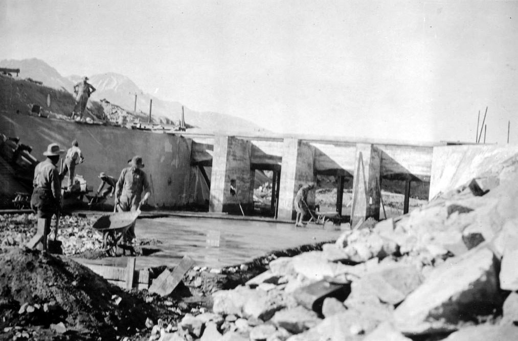
| (1912)* – Construction of regulating gates along the main canal in Owens Valley. |
| Historical Notes
The regulating gates along the main canal controlled the flow of water entering the aqueduct from the Owens River intake. Built to precise engineering standards, the gates allowed crews to increase, reduce, or completely shut off water flow during testing, inspection, and maintenance operations. Structures like these were among the least visible but most essential parts of the aqueduct. Along with spillways, measuring stations, and regulating works elsewhere on the route, they gave engineers the ability to control water movement across more than 200 miles of canals, tunnels, and siphons before the aqueduct entered full operation. |
 |
|
| (1913)* - Raising the intake gates near Aberdeen in Owens Valley. |
Historical Notes On February 13, 1913, workers raised the gates at the intake near Aberdeen, releasing Owens River water into the aqueduct for the first time. The controlled release allowed engineers to monitor flow conditions, inspect structures along the route, and identify any leaks or pressure problems before the aqueduct's formal dedication later that year. The release marked the transition from construction to operation. From the intake near Aberdeen, water began its gravity-fed journey more than 233 miles south through tunnels, lined canals, and steel siphons toward the San Fernando Valley. Although not a public ceremony, the February release represented the moment the aqueduct first functioned as a complete working system. |
* * * * * |
Map of the Los Angeles Aqueduct |
This map provides an overview of the full Los Angeles Aqueduct route as it was planned during the early stages of construction. Stretching more than 233 miles from Owens Valley to the San Fernando Valley, the aqueduct crossed some of the most remote and difficult terrain in California using a gravity-fed system of canals, tunnels, siphons, flumes, and pressure pipe. |
 |
|
| (ca. 1908)* - Map showing the full extent of the 233 mile long Los Angeles Aqueduct running from its intake in Owens Valley to the point at which the water cascades down into the northeast San Fernando Valley. |
| Historical Notes
This map, produced around 1908 as construction was beginning, shows the complete route of the Los Angeles Aqueduct from the Owens Valley intake in the eastern Sierra Nevada to the terminal cascades in the northeastern San Fernando Valley. The alignment crossed deserts, mountain ranges, fault zones, and broad valleys using a carefully engineered combination of canals, tunnels, siphons, flumes, and pressure pipe designed to maintain continuous gravity flow to Los Angeles. The map served both practical and public purposes. Engineers used route maps like this to coordinate construction across multiple divisions working simultaneously along the aqueduct, while city officials used them to explain the scale of the project to voters, newspapers, and critics who doubted that water could be carried more than 233 miles without pumping. For many residents of Los Angeles, maps like this provided the first clear visual understanding of the immense distance and terrain involved in bringing Owens Valley water to the city. |
* * * * * |
Final Tests Before Dedication
.jpg) |
|
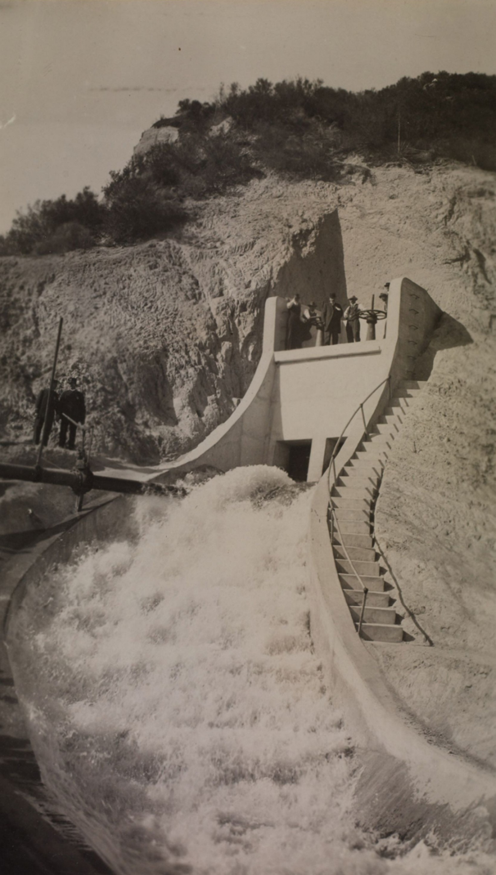
| (October 16, 1913)* - Test release of water at the San Fernando Valley cascades prior to the official dedication of the Los Angeles Aqueduct. |
Historical Notes Three weeks before the public dedication, engineers conducted a controlled test release at the San Fernando Valley cascades to verify that the system was performing as designed under full operating conditions. The October 16 test allowed crews to inspect the cascades, check gate mechanisms, and document the flow before the ceremony that would draw tens of thousands of spectators. The decision to conduct a formal test in advance reflected the same careful planning that had characterized the project from the beginning. The October test helped ensure that the dedication ceremonies proceeded without interruption when the public opening took place several weeks later. |
* * * * * |
The Aqueduct Is Officially Dedicated |
After five years of continuous construction, water from the Owens Valley reached Los Angeles in November 1913. The completion of the aqueduct was marked by public tests, ceremonial gate openings, and a formal dedication at the San Fernando Valley cascades. Tens of thousands attended the event, witnessing the moment Owens Valley water first reached Los Angeles. This section documents the dedication ceremonies and the culmination of one of the most ambitious engineering projects in American history. |
 |
|
| (1913)* – Opening of the Los Angeles Aqueduct headwater gates at Sylmar during the November 5 dedication ceremony. Among those at the wheels was H. A. Van Norman, Owens Valley division engineer and namesake of today's Van Norman Reservoir. Others included Roderick Mackay, D. L. Reaburn, A. C. Hansen, and Adna R. Chaffee, Jr. Photo from the Ernest Marquez Collection. |
Historical Notes The men shown here turning the headwater gates on November 5, 1913, were not ceremonial figures — they were the engineers and division superintendents who had built the system. H. A. Van Norman had overseen construction of the Owens Valley division, including the electric dredge operations on the unlined canal. A. C. Hansen had managed the demanding Jawbone division and its 52-mule pipe hauls. Roderick Mackay had supervised the cement operations and heavy equipment selection across the project. Their presence at the gates on dedication day reflected William Mulholland’s understanding of what the occasion represented to the men who had carried out the work across more than 233 miles of desert, mountain, and valley terrain. |
 |
|
| (November 5, 1913)* - Crowds watch as water is released from the gates at the top of the cascades during the dedication ceremony. William Mulholland can be seen slightly right of center above the American flag. |
Historical Notes More than 30,000 people gathered at the San Fernando Valley cascades on November 5, 1913, to witness the formal opening of the Los Angeles Aqueduct. When the gates were opened and water began its descent, William Mulholland turned to the crowd and spoke the words that have defined the moment ever since: “There it is. Take it.” The brevity was characteristic — five years of construction, 233 miles of canals, tunnels, and siphons, and thousands of workers reduced to a single sentence. The crowd’s response, flags waving and cheers rising as water filled the cascades, reflected years of anticipation in a city that had been told the aqueduct would secure its future. |
 |
|
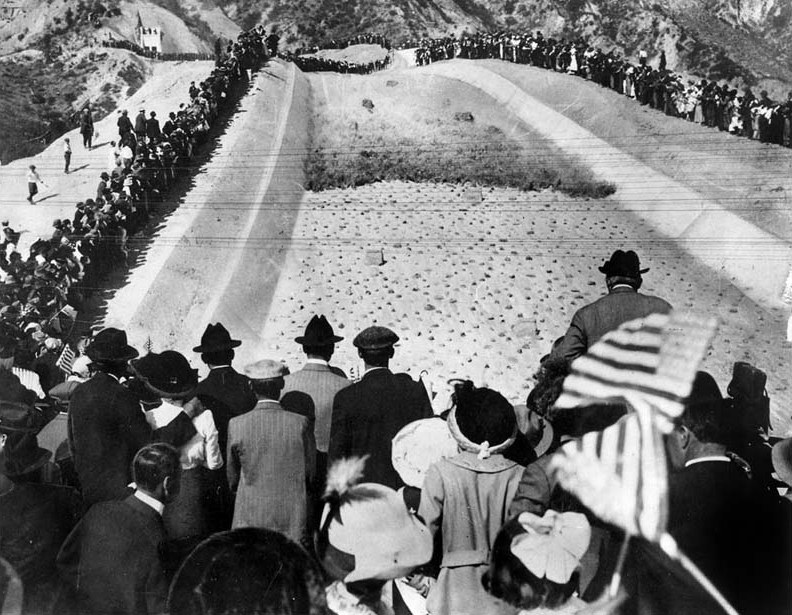
| (November 5, 1913)* - Crowds gather near the San Fernando Valley cascades as Los Angeles Aqueduct water flows publicly for the first time. |
Historical Notes This view from the cascades captures both the scale of the gathering and the moment the aqueduct became visible to the public as a working system. The cascades at Sylmar marked the terminal point of the gravity-fed route, where water descending from the aqueduct outlet entered the city’s distribution system. Photographs taken during the November 5 dedication ceremonies became some of the most widely reproduced images in Los Angeles history, appearing in newspapers, anniversary publications, and historical accounts for decades afterward. They documented not only the engineering achievement itself, but the public reaction to the arrival of Owens Valley water in Los Angeles. |
Legacy of the Aqueduct
Construction of the LA Aqueduct Video
Click HERE to see a short (5 min.) video titled: 'The Great Los Angeles Aqueduct' |
 |
|
| (1915)* – Early automobile passing the terminus of the Los Angeles Aqueduct near present-day Sylmar, two years after the aqueduct’s completion. |
Historical Notes By 1915 the cascades at Sylmar had become a recognizable landmark along the main route connecting Los Angeles to the San Joaquin Valley. The aqueduct terminus and the Ridge Route highway, both completed within a few years of one another, reflected the infrastructure projects that were reshaping Southern California during the early automobile era. The automobile in the photograph is a reminder of how quickly the landscape around the terminus was changing. In 1913 many visitors had arrived at the dedication ceremony by special rail excursion. Only a few years later, motorists were already traveling past the cascades on journeys between Los Angeles, Bakersfield, and the Central Valley. |
 |
|
| (1918)* - Sign marking the terminus of the Los Angeles Aqueduct near present-day Sylmar, five years after the system's completion. The original cascade is visible at left. |
Historical Notes This photograph, taken in March 1918, shows the sign installed at the southern terminus of the Los Angeles Aqueduct near present-day Sylmar, not far from where Interstate 5 runs today just east of the Van Norman Reservoir. The San Gabriel Mountains are visible to the north in the background, just east of Newhall Pass. The sign reads: "Terminus of the Los Angeles Aqueduct. Length 233 Miles. Capacity 260 Million Gallons Daily." The cascade visible to the left marked the functional endpoint of the gravity-fed system, where water descending from the aqueduct outlet entered the city's distribution network. The sign itself served as a public summary of what the project had accomplished — 233 miles of canals, tunnels, and siphons delivering 260 million gallons daily to a city that was growing faster than almost anywhere else in the country. |
 |
|
| (2013)* - Visitors gathered at the original Los Angeles Aqueduct cascade during the system’s 100th anniversary celebration. The Second Los Angeles Aqueduct cascade is visible at right. |
Historical Notes This photograph was taken during the centennial observance of the Los Angeles Aqueduct in 2013, marking 100 years since the system first delivered Owens Valley water to Los Angeles. Visitors gathered at the original cascade near Sylmar, where the dedication ceremony had taken place on November 5, 1913. The image also shows the cascade associated with the Second Los Angeles Aqueduct, completed in 1970 to increase delivery capacity and improve operational flexibility within Los Angeles’ expanding water system. |
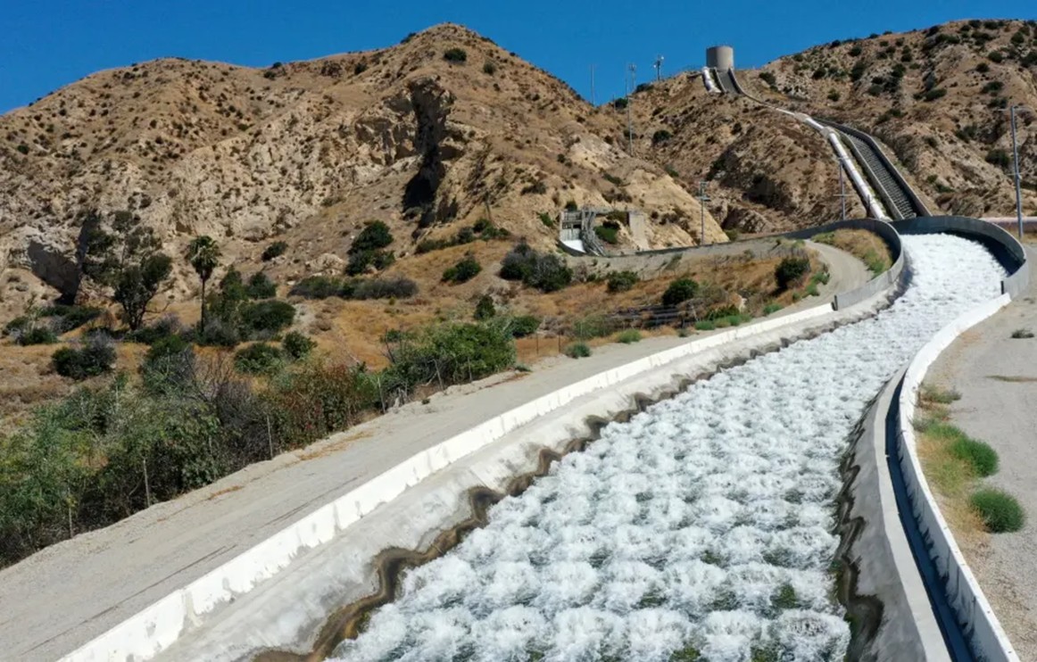 |
|
| (2022)* - Water flows down the original Los Angeles Aqueduct cascade at Sylmar, while the Second Aqueduct cascade at right remains dry. Photo by Dean Musgrove, Los Angeles Daily News/SCNG. |
Historical Notes In normal operation, the hydroelectric plants handle the full volume of incoming water, so most or all water bypasses the cascades and flows through the penstocks for power generation. As a result, water flowing down the cascades is now an occasional event rather than a daily occurrence. The cascades continue to serve as overflow and operational control structures, providing flexibility during maintenance periods, repairs, and unusually high flow conditions. Together, the original and Second Aqueduct cascades illustrate more than a century of continued evolution within Los Angeles’ water system. Click HERE to see more on the Second Los Angeles Aqueduct. |
Historical Background Video (w/Catherine Mulholland)
Click HERE to see a short (4 min.) video on the Construction of the Los Angeles Aqueduct |
Los Angeles Aqueduct History and Photos |
Research, writing, and image curation by Jack Feldman, Water and Power Associates, with editorial assistance.
* * * * * |
More Historical Early Views
Newest Additions
Early LA Buildings and City Views
History of Water and Electricity in Los Angeles
* * * * * |
References and Credits
* DWP - LA Public Library Image Archive
^ YouTube - Construction of the Owens Valley Project
^^LADWP Publication: The Story of the Los Angeles Aqueduct
^*Santa Clarita Valley History in Pictures (Photo Credit - Alan Pollack)
^#OwensValleyHistory.com: Terminus of the L.A. Aqueductt; Antelope Valley; Cement Mill; Steam Shovel No. 1
*#Skyscraperage.com - LA Times: June 18, 1911 LA Aqueduct
**#California State Library Image Archive
^*#Calisphere: University of California Image Archive
^#^Construction Photos of Joseph Barlow Lippincott
^^*L.A. Aqueduct Centennial 2013
*#*Virtual Transportation Museum
*^^A History of the San Fernando Valley: lahistoryarchive.org
^^^California Museum: Today in CA History
*^*Wikipedia: Cowley County Historical Museum - Caterpillar Tractor Photo; Monolith, CA
**^William Mulholland and the Rise of Los Angeles by Catherine Mulholland
< Back