Construction of the Los Angeles Aqueduct
Introduction |
Between 1908 and 1913, the City of Los Angeles undertook one of the most ambitious public works projects of its era: the construction of the Los Angeles Aqueduct. Designed under the direction of Chief Engineer William Mulholland, the gravity-fed system brought water more than 233 miles from the Owens Valley to a rapidly growing city in Southern California. At the time of its completion, the aqueduct was widely regarded as one of the greatest engineering achievements in the world, rivaled only by the Panama Canal.The images and notes in this section trace the story of how the aqueduct was planned, built, and put into operation. They follow the project from early surveys and engineering reviews through tunneling, concrete work, power generation, and the immense logistical challenge of moving men, materials, and machinery across deserts, mountains, and remote terrain. Together, these photographs document not only the construction of a water system, but the people, labor, and ingenuity that made it possible—and the moment when water from the Owens Valley finally reached Los Angeles. |
Historical Background |
The Los Angeles Aqueduct was designed and constructed by the City’s water department, then known as the Bureau of Los Angeles Aqueduct, under the direction of Chief Engineer William Mulholland. Built between 1908 and 1913 at a cost of approximately $23 million, the aqueduct tapped the Owens River and carried water more than 233 miles south to Los Angeles. Upon its completion in 1913, it was widely regarded as one of the greatest engineering achievements of its time. More than a century later, the gravity-fed system remains a vital part of the city’s water supply, delivering a significant share of Los Angeles’s water in an average year. |
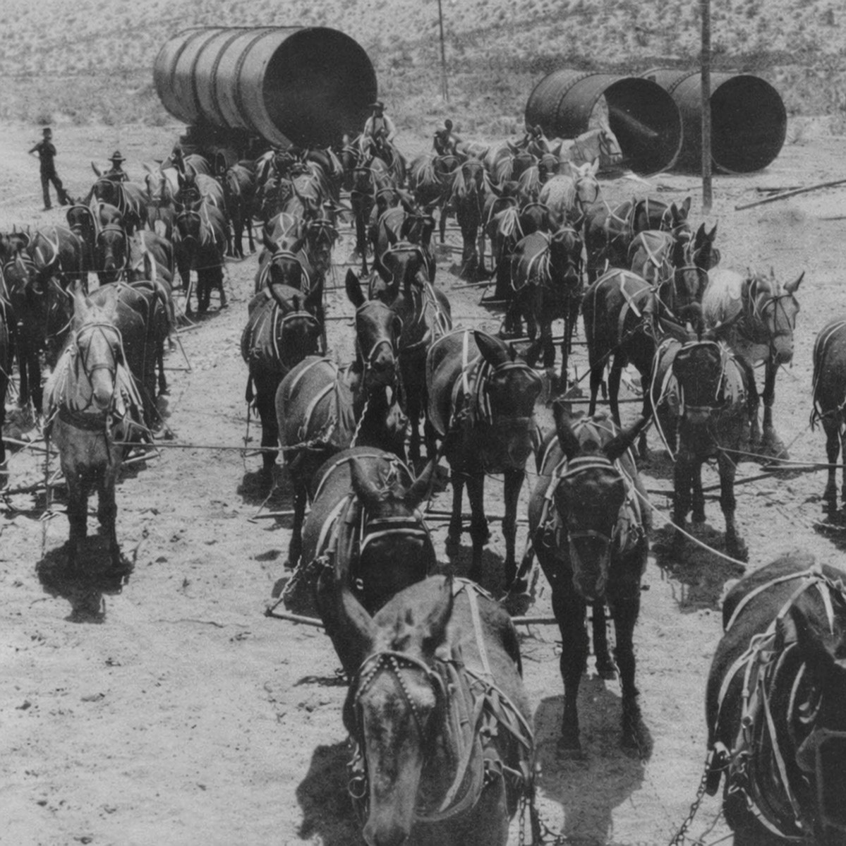 |
| (1912)* - Transportation was largely by mule power when the Los Angeles Aqueduct was under construction. This photo shows a 52-mule team hauling sections of aqueduct pipe to the Jawbone Siphon. |
* * * * * |
Planning, Approval, and the People at the Top |
Before construction could begin, the Los Angeles Aqueduct existed only as an ambitious proposal. City leaders needed to demonstrate that a gravity-fed aqueduct spanning deserts, mountains, and remote terrain was both feasible and reliable. Funding required voter approval, and nationally respected engineers were invited to independently review the plans. This section introduces the individuals who shaped the project at its highest level, including William Mulholland, the advisory engineers, and the city officials who guided the aqueduct from concept to construction. |
 |
|
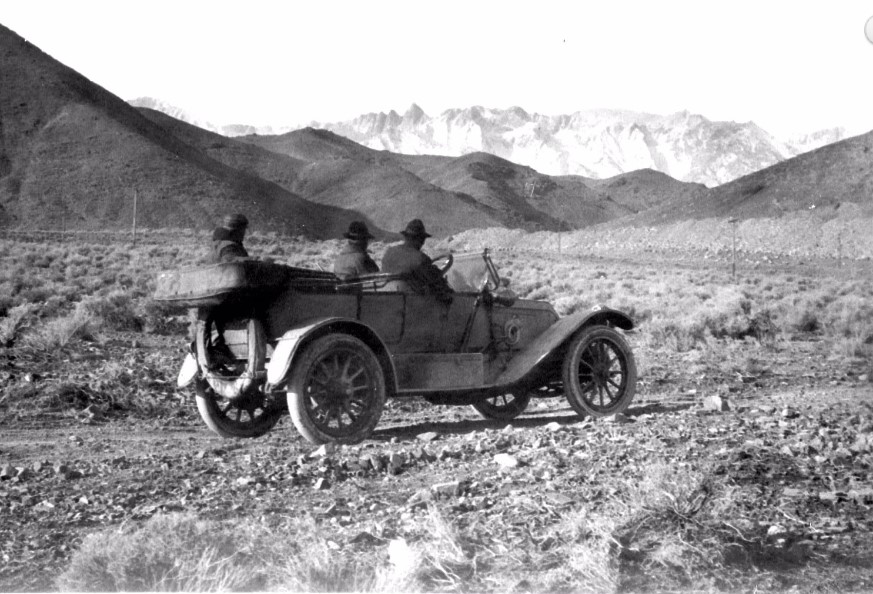
| (ca. 1906)*– View showing William Mulholland along with two others, sitting in a car in the Owens Valley. All three are looking toward the snow covered Eastern Sierras, water source of the yet to be built L.A. Aqueduct. |
| Historical Notes
In March of 1905, William Mulholland recommended to the Board of Water Commissioners that the Owens Valley was the only viable source of supplemental water for the City’s fast growing population. The following year the City submitted an application for rights-of-way across federal lands for the purpose of constructing an aqueduct. The application was approved and in 1907 Los Angeles voters approved a $23 million bond issue for the construction of the Los Angeles Owens Valley Aqueduct. Work began on the aqueduct in September and the City began to purchase private property and water rights in the southern pert of Owens Valley.^^* |
 |
|
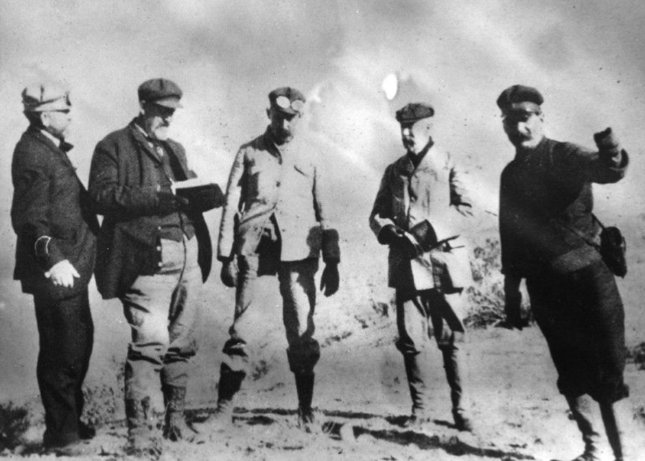
| (1906)* - The independent Board of Engineers appointed to review Mulholland’s scheme for the Los Angeles Aqueduct in the Owens Valley. From left, John R. Freeman, James D. Schuyler, Joseph P. Lippincott, Frederick P. Stearns, and William Mulholland. |
| Historical Notes
Seeking to diminish as much criticism as possible prior to the $24 million bond election, the Los Angeles Water Commissioners appointed an Aqueduct Advisory Board, comprised of three nationally known civil engineers: John R. Freeman, James D. Schuyler and Frederick P. Stearns. They made an independent evaluation of the proposed aqueduct. The board reviewed the project's design feasibility, constructability, pricing and logistic requirements. The Board found the aqueduct "admirable in conception and outline" in their report released during the fall of 1906. Few engineers dared to criticize the project after the panel's review was released, due in large part to the clout and credibility of John R. Freeman, one of the principal consultants for New York’s New Croton Aqueduct.^ |
 |
|
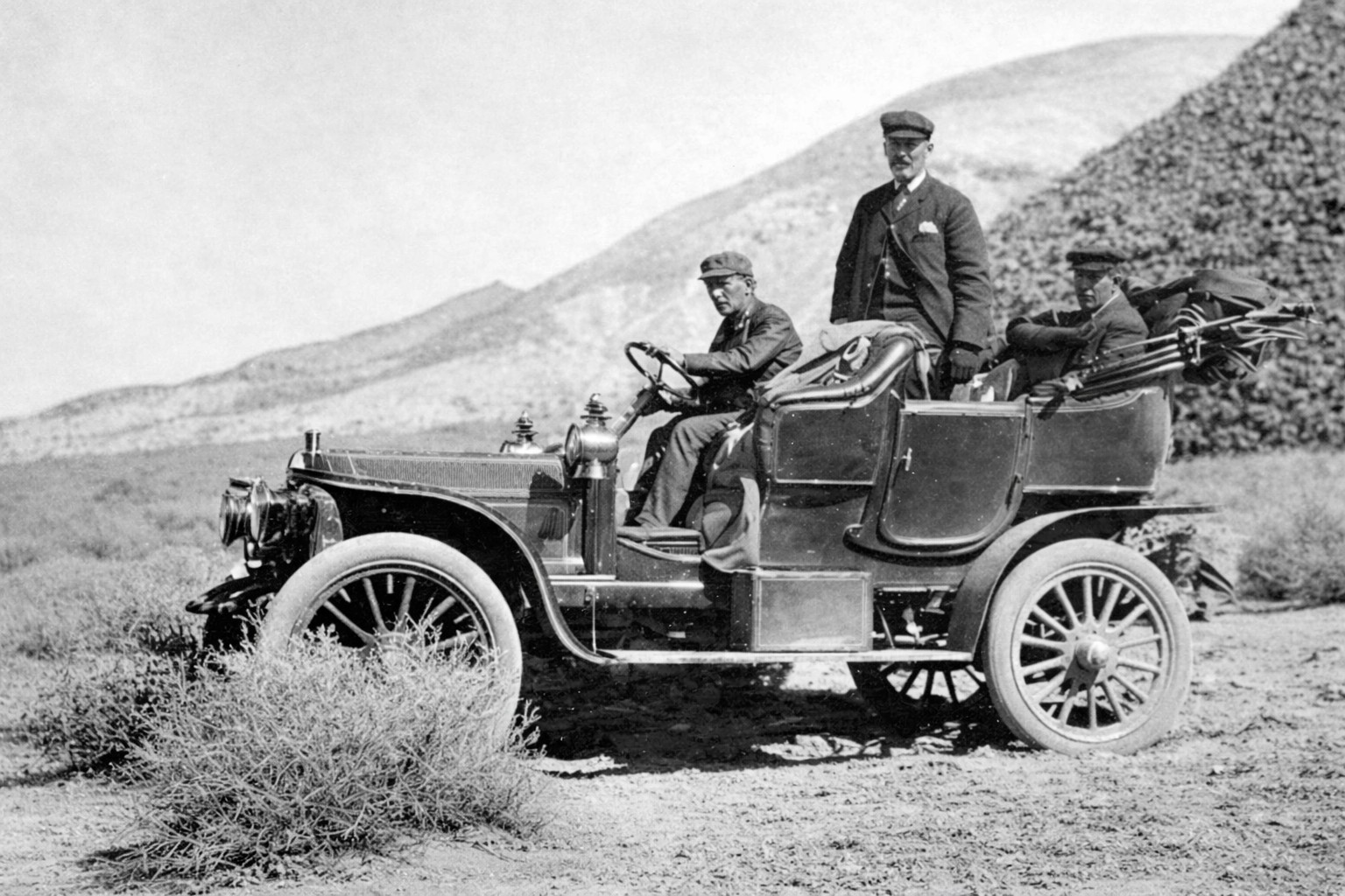
| (1906)* – James D. Schuyler, nationally recognized Civil Engineer and member of the Aqueduct Advisory Board, looks out toward the landscape as he evaluates the feasibility of constructing the aqueduct. |
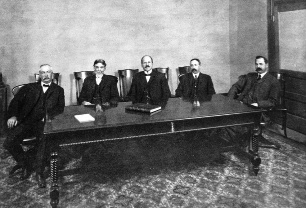 |
| (ca. 1905)* - The Board of Water Commissioners of the LA Department of Water and Power at the time of the building of the LA Aqueduct to Owens Valley. (L-R) John J. Fay, J. M. Elliott, Moses H. Sherman, William Mead, and Fred L. Baker. |
| Historical Notes
Moses Sherman served on the water board while he also participated in plans to develop the San Fernando Valley, which became the outlet point for the aqueduct. Sherman's double role has been the source of conspiracy theories with regard to the aqueduct.* |
* * * * * |
Construction Divisions and Leadership |
Constructing the Los Angeles Aqueduct required careful organization and clear lines of authority. The project was divided into divisions, each overseen by engineers responsible for specific geographic sections and types of work. This structure made it possible to coordinate thousands of workers, multiple construction sites, and a wide range of tasks, including tunneling, concrete work, power generation, and material transport. This section outlines how the aqueduct’s construction effort was organized and managed across its vast length. The organizational chart and key assignments below show how the city structured the work across divisions. |
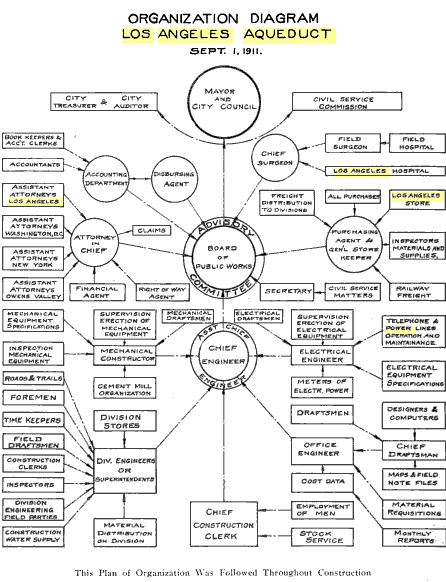 |
The Board of Public Works had charge of the expenditure of all bond moneys derived from the sale of Aqueduct and Power bonds.
William Mulholland was appointed the Chief Engineer.
J.B. Lippincott was appointed Assistant Chief Engineer. |
| (1911)*- Organizational Chart for the Construction of the LA Aqueduct. |
Key construction roles included the following assignments: H. A. Van Norman was in charge of the construction work done with dredges and the building of the unlined canal on the Owens Valley division. O.W. Peterson was in charge of the construction of the open lined canal from the north end of the Alabama Hills to the Haiwee reservoir. Phil Wintz had charge of the building of the South Haiwee Dam. C. H. Richards was in charge of the construction of the covered conduits and tunnels in the Rose Valley and Little Lake divisions. F. J. Mills was Division Engineer of the Grapevine division, consisting of tunnels and pressure pipes. Louis Mesmer built the Freeman Division. A. C. Hansen completely constructed the Jawbone division and a large portion of the Mojave division. John Gray had charge of the greater portion of the construction of the Elizabeth Tunnel and the power tunnels in the San Francisquito Canyon. W. C. Aston was in charge of the south portal of the Elizabeth tunnels and steel pipe. E. F.Scattergood was Electrical Engineer in charge of construction of the power plants. Roderick MacKay had general supervision of the operation of the cement mill and of the selection and advisory of the heavy mechanical equipment. E. W. Bannister was Office Engineer in general charge of the drafting room and of the office of records. |
* * * * * |
Tunneling: The Hardest Work |
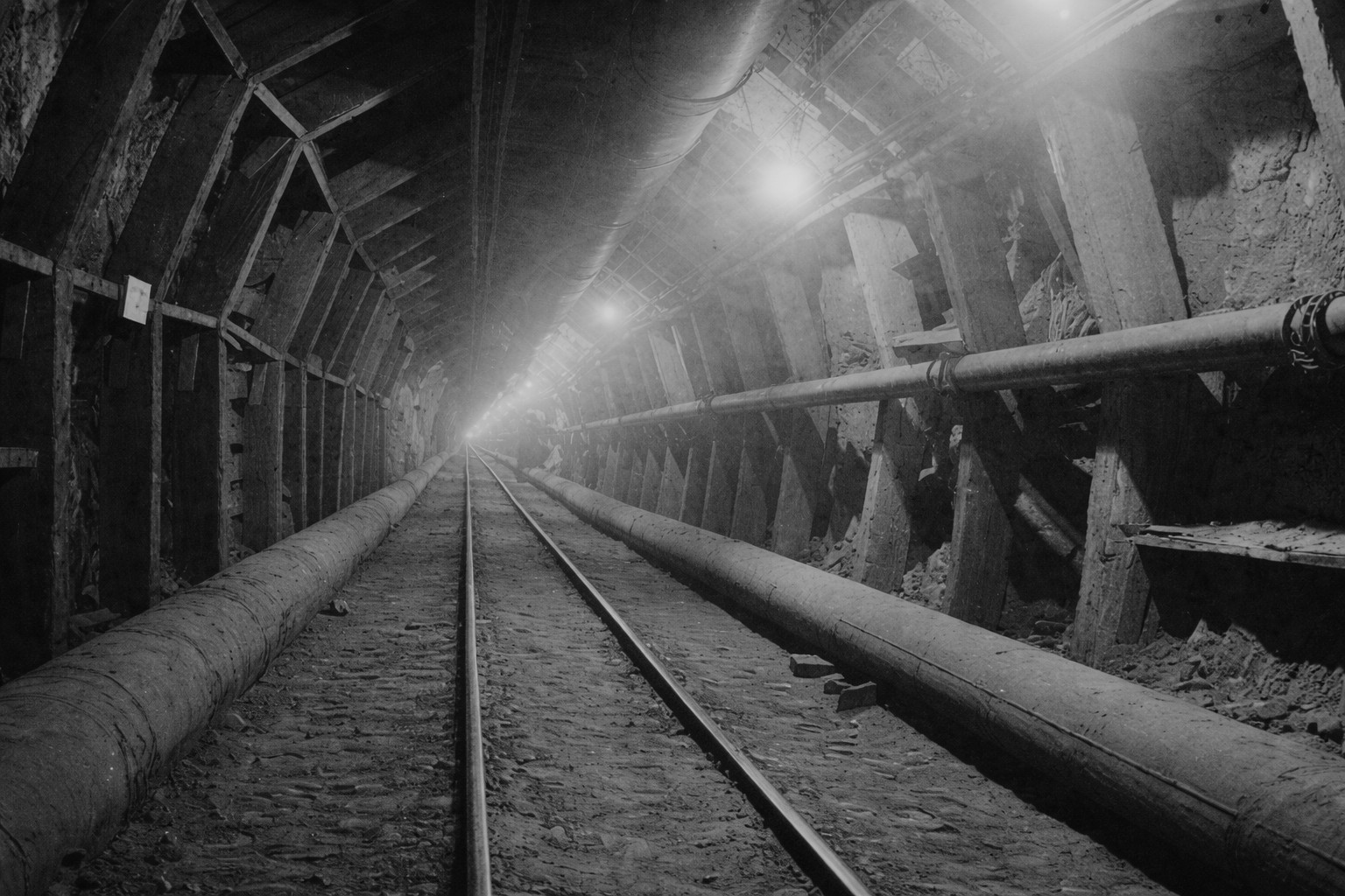
Tunneling was the most demanding and hazardous phase of aqueduct construction. More than 140 tunnels, totaling over forty miles, were driven through solid rock in isolated locations with limited access to supplies. Crews relied on hand drilling, explosives, and early mechanical equipment while working in extreme heat, dust, and confined spaces. The success of the aqueduct depended heavily on this work, particularly on major tunnels such as the Elizabeth Tunnel, which tested both engineering methods and human endurance. |
 |
|
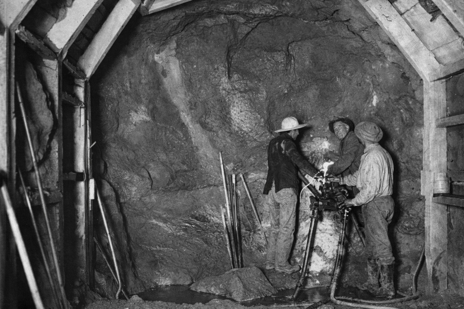
| (ca. 1908)* - View of a construction crew drilling in the Elizabeth Tunnel. |
| Historical Notes
The most difficult part of the construction of the LA Aqueduct was tunneling. There were 142 tunnels, totaling forty-three miles in length, that had to be dug during the five years of the aqueduct's construction. The Elizabeth Tunnel was the longest with a length of over five miles.* |
 |
|
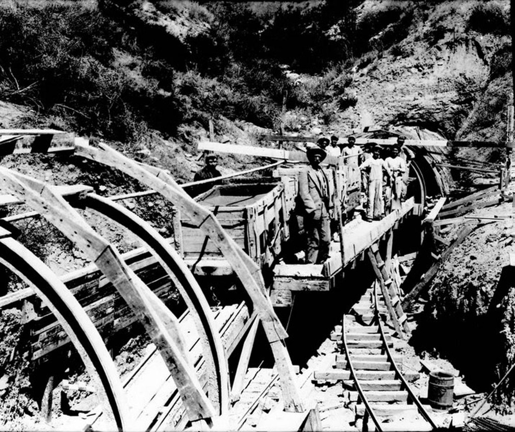
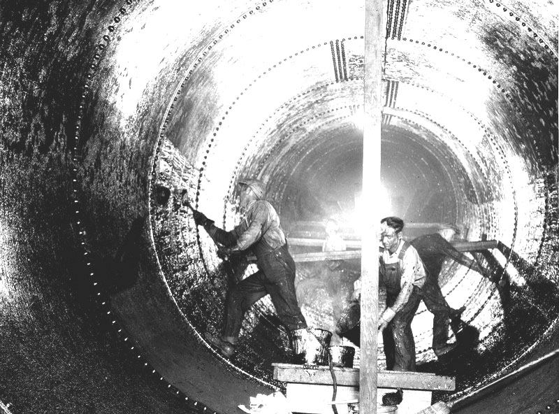
| (ca. 1908)* - Workers preparing tunnel for cement lining. |
 |
|
| (1910s)* - Tunnel construction nearing completion. |
 |
|
| (1908)* - Men pose in front of the Elizabeth Tunnel at Johnsville, California. |
| Historical Notes
Click HERE to see more in Tunnel Construction on the LA Aqueduct |
* * * * * |
Moving Men and Materials: Tractors and Mule Power |
Transporting materials across deserts and mountain terrain posed constant challenges during construction of the aqueduct. Engineers experimented with new technologies, including early caterpillar tractors, in hopes of replacing traditional mule teams. While these machines showed promise, difficult terrain and frequent mechanical failures often forced crews to rely on animal power. This section documents the parallel use of tractors and mule teams and shows how practical experience ultimately determined which methods succeeded in the field. |
 |
|
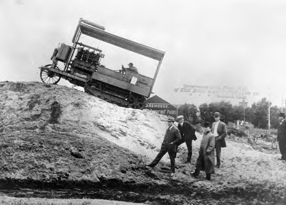
| (1907)* - The first Caterpillar tractors ever built were used to help complete the 5.5 mile Elizabeth Lake Tunnel section of the Los Angeles-Owens River Aqueduct. |
| Historical Notes
“It crawls like a caterpillar.” And caterpillar is its name to the present day. The descriptive remark is attributed to William Mulholland while watching the first formal demonstration of the new type of tractor just purchased for hauling materials across the desert during the building of the aqueduct. |
 |
|
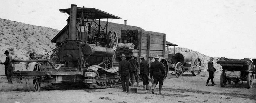
| (1908)* - Caterpillar Traction Engine hauling lumber on the Mojave Desert. |
| Historical Notes
The Holt caterpillar traction engines looked so promising that 28 of them were purchased by the City for transporting heavy loads. |
 |
|
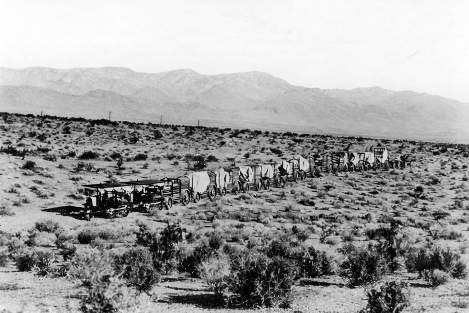
| (1909)* - Two Holt 45 gas crawling-type ("caterpillar") tractors team up to pull a long wagon train in the Mojave Desert during construction of the Los Angeles Aqueduct. |
| Historical Notes
It was hoped that the Caterpillar tractor would be a mechanical substitute for the mule – a departure from traditional construction methods that could lower costs and speed the progress of the great water way to Los Angeles. However, things didn’t quite work out that way. |
 |
|
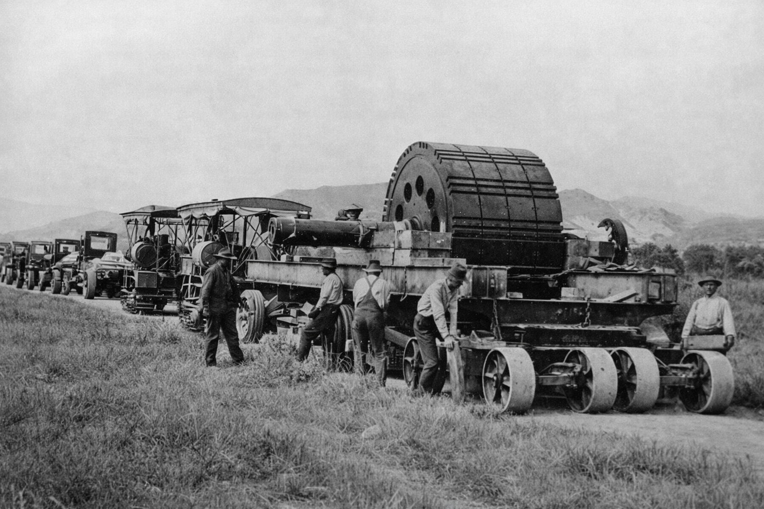
| (ca. 1910)* - Truck fleet and Holt caterpillar traction engine transporting materials and machinery to an aqueduct construction site. |
| Historical Notes
The Mojave Desert proved too much of a challenge for the caterpillar traction engines. They were plagued with frequent breakdowns and their use was soon abandoned in favor of mule teams. Some of the Holt caterpillars were used as forms when the concrete lining of the aqueduct was poured. |
 |
|
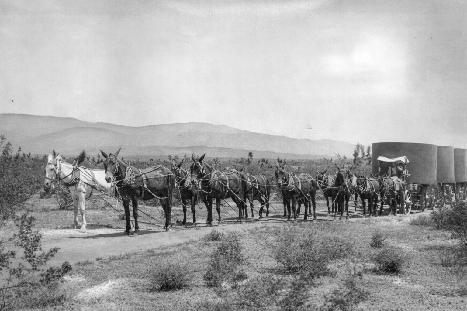
| (ca. 1910)* - Mule team hauling materials to build the Los Angeles Aqueduct. The roadless territory spanned by the $24,500,000 water system was too tough for the automotive travel of that era. |
| Historical Notes
City crews reverted back to using mules after maintenance and repair of the caterpillar tractor proved too costly. |
* * * * * |
Whistling Dick and the 52-Mule Teams
 |
|
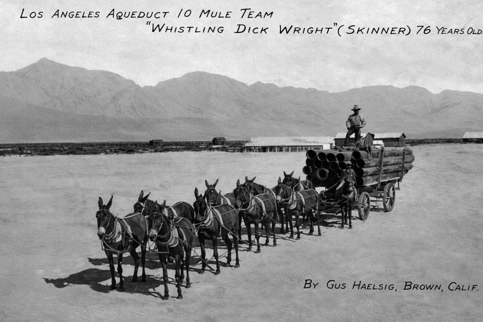
| (1912)* - Early postcard depicting 10 mule team hauling equipment during aqueduct construction. |
| Historical Notes
Early postcard depicting “Whistling Dick”, a 76 year old muleskinner who worked on the aqueduct; postcard was loaned for copy purposes by Department of Water and Power retiree Ed Fleming of Mojave (June 1971). Fleming stated that the picture shows Dick Wright mounted on the left wheel mule holding the jerk line, and his two swampers are atop the load of pipe. “Whistling Dick” had the makings of both myth and legend, a type of rugged individual who creates an aura of romance in stories of the Old West. Back in 1912, 74-year-old Whistling Dick drove a team of 52 balky mules as he labored with hard working crews building one of the toughest sections of the Los Angeles Owens River Aqueduct in the Mojave Desert – the spectacular jawbone Siphon, a giant roller coaster of a pipeline. What is considered to be Whistling Dick’s grave is in a small windswept cemetery about one mile southwest of Jawbone Canyon Road, located between the routes of the original and the Second Los Angeles Owens River Aqueducts. His 52-mule team wagons transported mammoth 30-ton sections of steel pipe along sun baked desert trails to the job sites. Although 20-mule teams were common, the extremely heavy aqueduct sections required the pulling power of the 52-mule teams. |
* * * * * |
Concrete, Cement, and the Monolith Plant |
Concrete formed the structural backbone of the Los Angeles Aqueduct, lining miles of open channel, conduits, tunnels, and siphons. To ensure a reliable supply, the City established its own cement production facility near Tehachapi at a site that became known as Monolith. From quarrying raw materials to milling, bagging, and transport, this operation supported construction across the entire route. This section documents how cement was produced and applied and highlights the critical role the Monolith plant played in one of the largest public works projects of its era. |
 |
|
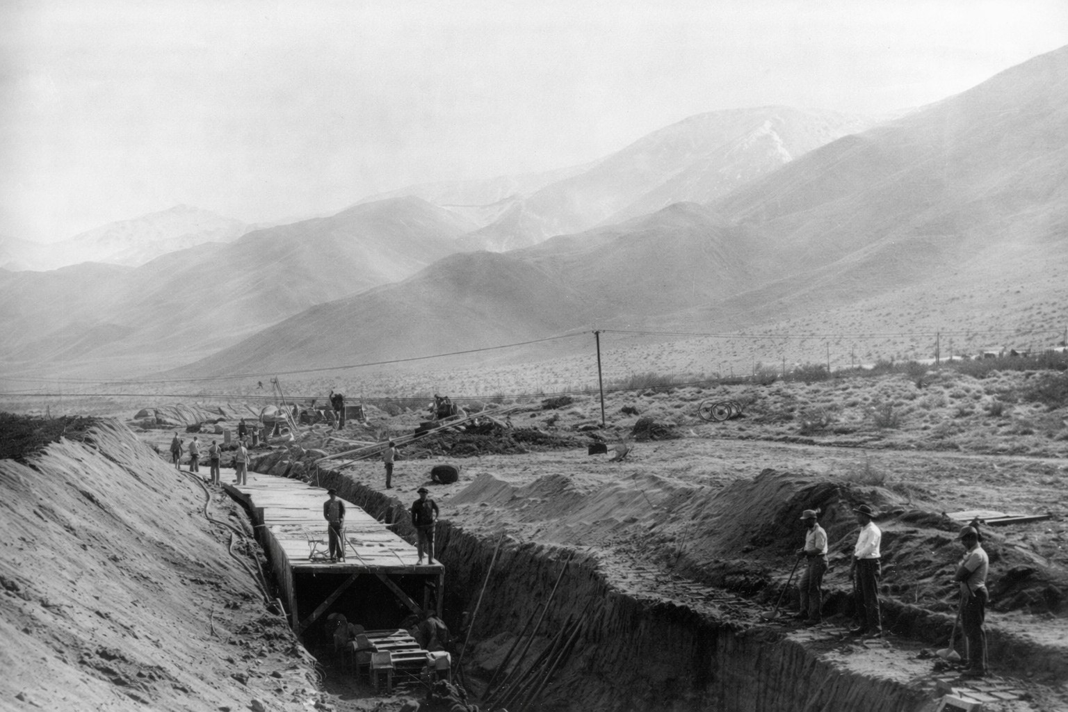
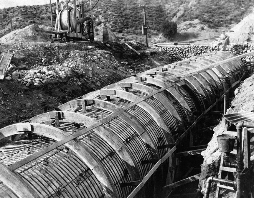
| (ca. 1910)* - Forms for cement lining are being put in place at an open channel section of the LA Aqueduct. |
 |
|
| (1908)* - Workers begin the process of cement lining the open channel portion of the LA Aqueduct. |
| Historical Notes
Concrete was the most prevalent construction material for the Aqueduct, although in some cases the engineers might have preferred steel pipe. The use of steel pipe was limited by its tremendous cost, a result of having to transport it to California from its place of manufacture in Pennsylvania. |
 |
|
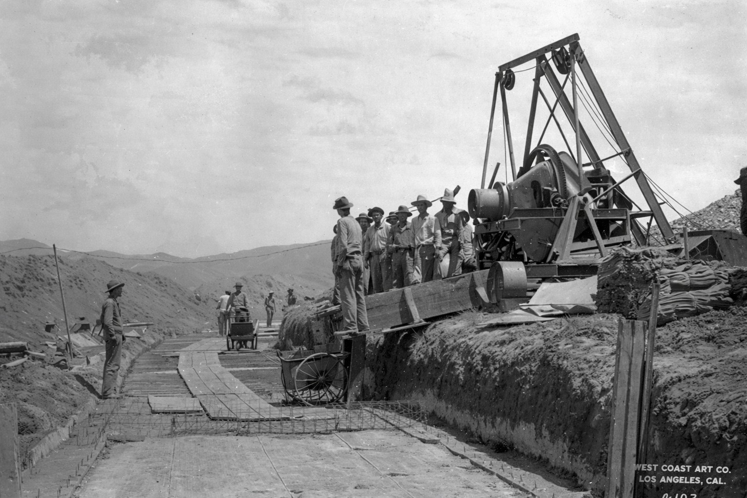
| (1908)* - On-site cement plant was used for the lining of the open channel portion of the aqueduct. |
 |
|
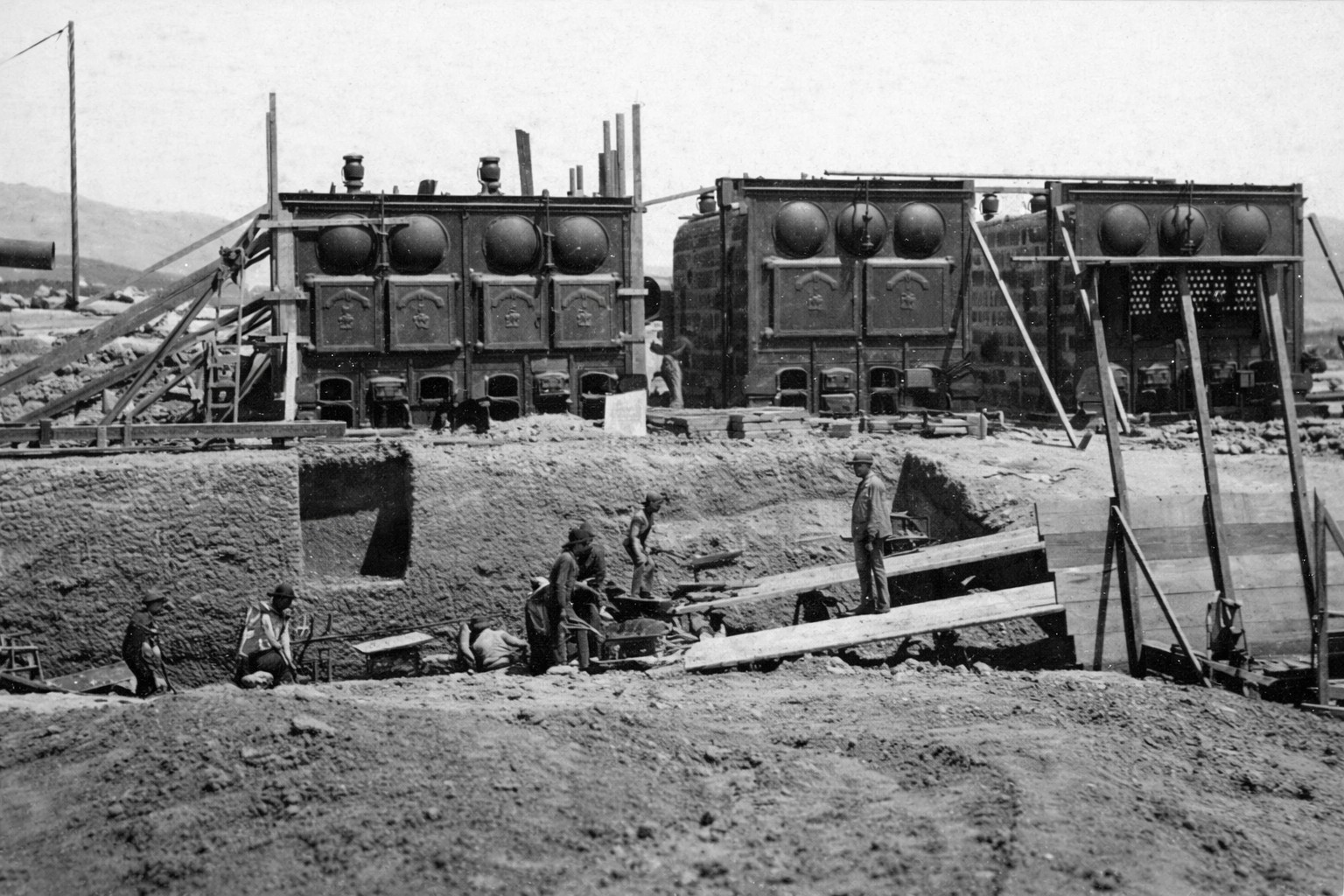
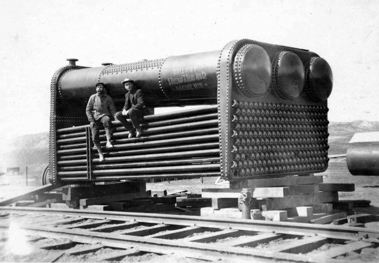
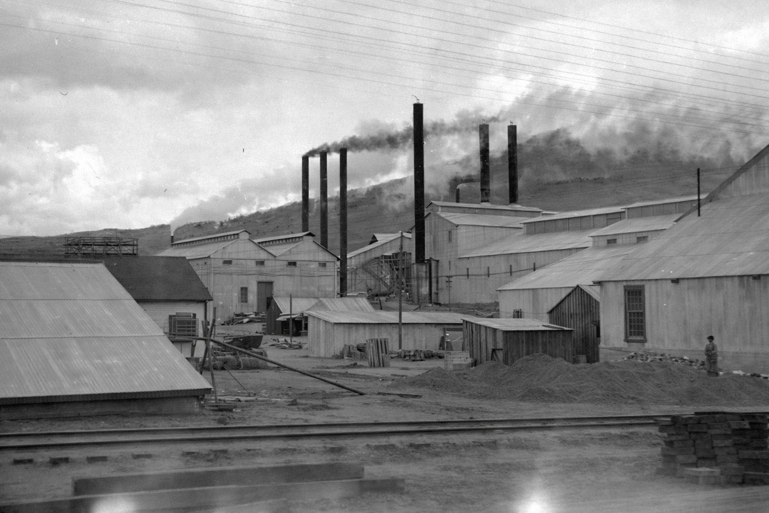
| (ca. 1908)* - Close-up view of cement mill boilers. |
 |
|
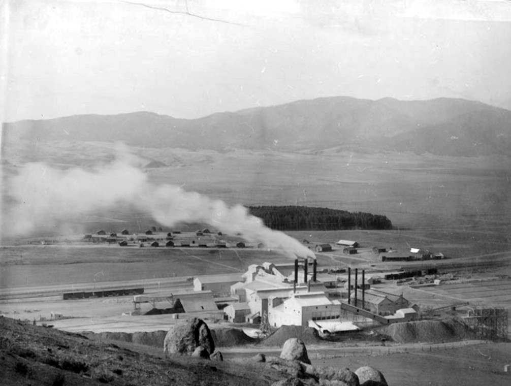
| (1909)* - View of the cement plant built for the construction of the LA Aqueduct, named Monolith. |
| Historical Notes
Monolith began as a camp for workers at a cement plant supplying the Owens Valley aqueduct. William Mulholland bestowed the name due to a huge limestone deposit. The Aqueduct post office opened in 1908, and changed its name to Monolith in 1910. |
 |
|
| (1909)* - Closer view of Monolith where a great portion of the cement was produced for the aqueduct's construction. |
Historical Notes Cuddleback Ranch, five miles east of Tehachapi, was on the main line of the Southern Pacific. There the city found the materials for making 1000 barrels of Portland cement a day. They purchased 4,300 acres of land covering limestone quarries, clay deposits, and deposits of tufa also used for making concrete. In addition to the cement produced at the Monolith Mill built at Cuddleback Ranch, the City also used 200,000 barrels of cement bought from other sources. |
 |
|
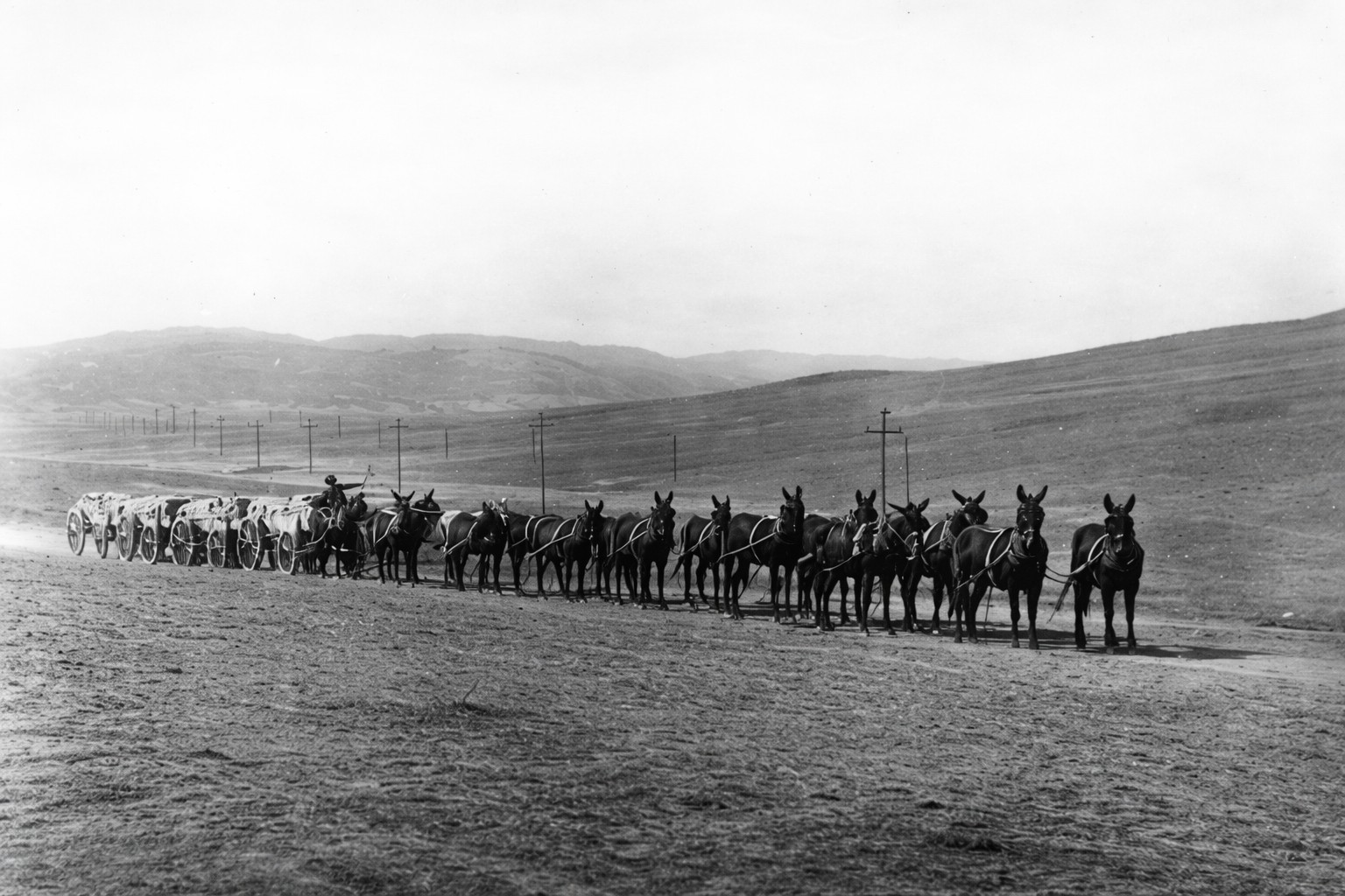
| (ca. 1912)* - A 16-mule team hauling bags of cement produced at the Monolith plant in the Tehachapi Mountains. |
| Historical Notes
Cement bagged at the Monolith Mill was shipped by train to the nearest railroad siding, then loaded onto wagons and transported by mule team to aqueduct construction sites. |
 |
|
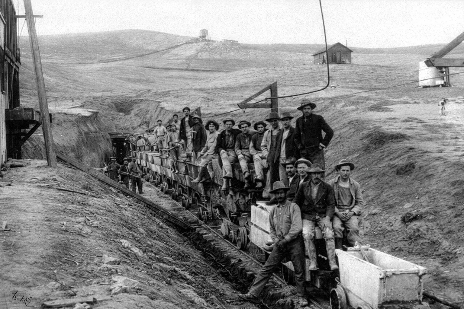
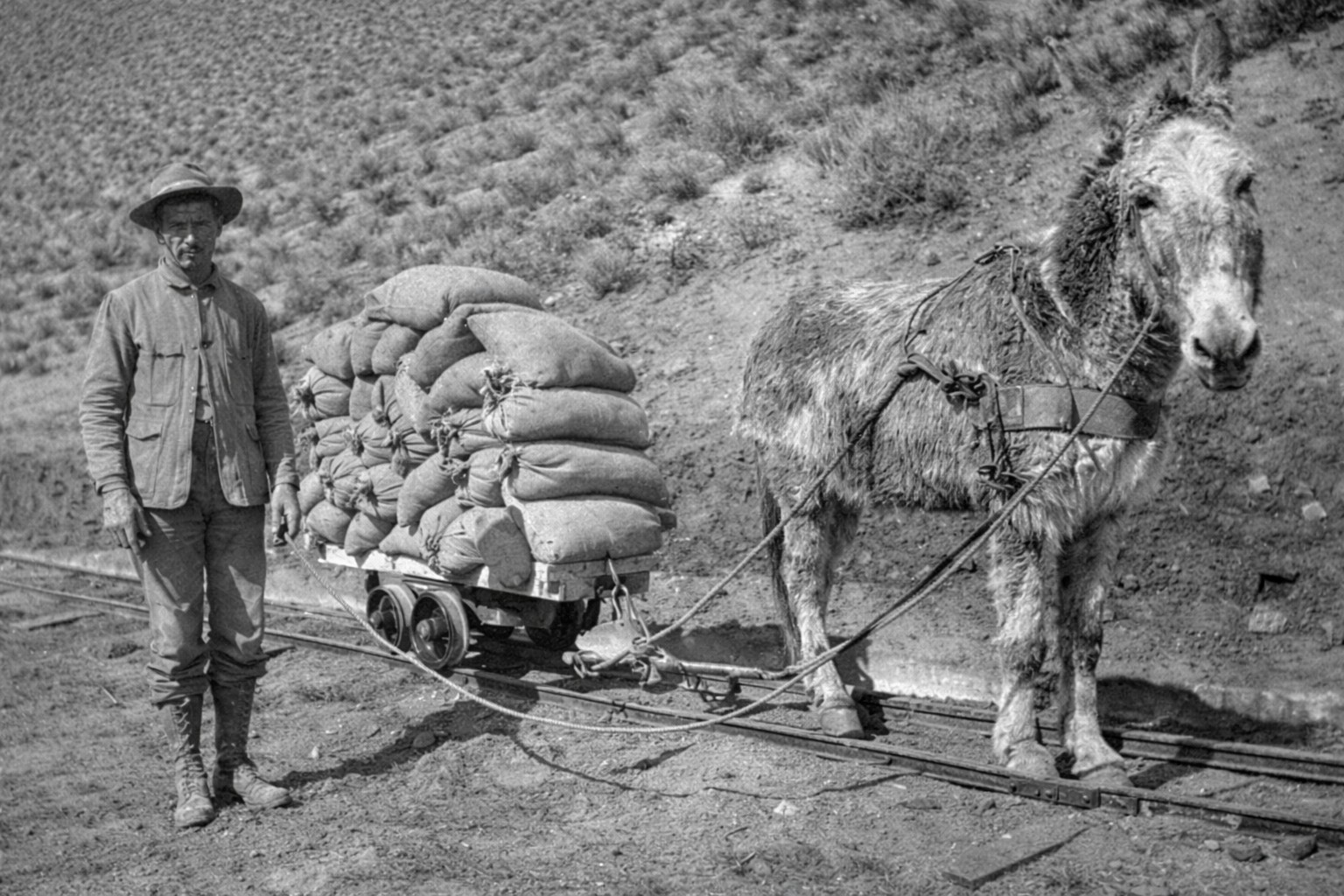
| (1908)* - Vew of a worker with mule-drawn small rail car transporting cement to a construction site. |
* * * * * |
Camps, Crews, and Daily Life Along the Aqueduct |
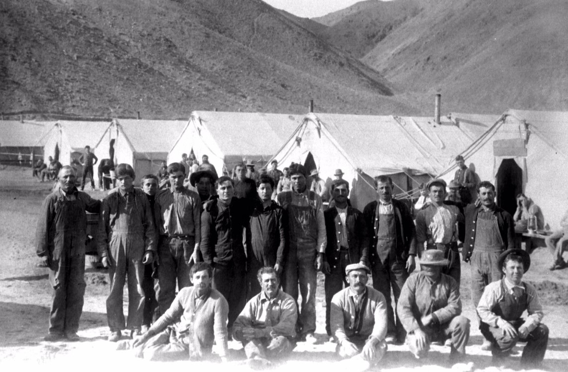
Thousands of men lived and worked along the aqueduct route during its construction, often in isolated camps far from towns or rail lines. Crews endured harsh weather, long hours, and difficult conditions while building tunnels, canals, and pipelines. This section offers a glimpse into daily life along the aqueduct, showing the workers, camps, and support facilities that made continuous construction possible. |
 |
|
| (ca. 1912)^*– Group photo of workers posing in front of their living quarters before the start of a long workday. |
 |
|
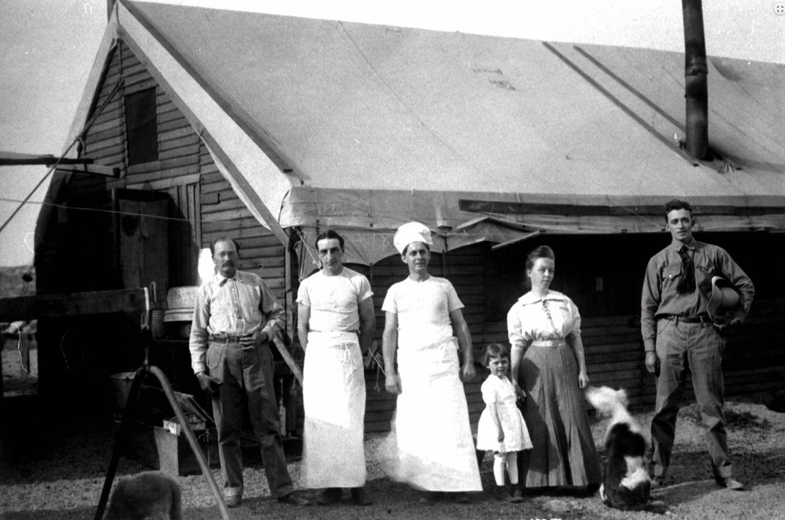
| (ca. 1912)^*– View showing some of the cooks and possibly family posing in front of the mess hall. |
 |
|
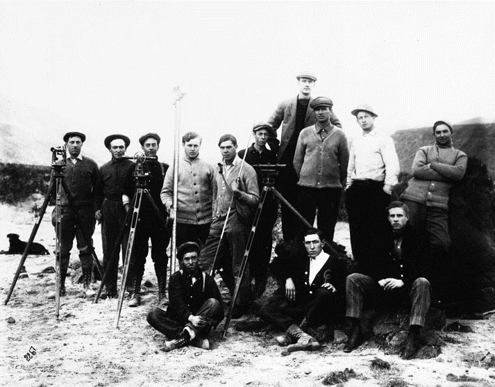
| (n.d.)* - Surveying crew during the LA Aqueduct construction. |
* * * * * |
Powering the Construction: Hydroelectric Plants and Electricity |
Electric power played a critical role in the construction of the Los Angeles Aqueduct. To supply energy in remote areas, the City built hydroelectric plants along the aqueduct route, including Division Creek and Cottonwood. This power was used to operate dredges, run machinery, and support cement production at Monolith. The use of electricity on such a large scale during construction was unprecedented and allowed work to proceed faster and more efficiently across long distances. |
 |
|
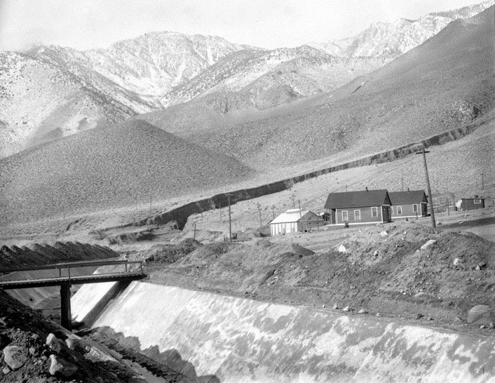
| (ca. 1908)* - Cottonwood Power Plant started generating 900 kilowatts of hydroelectric power along the Los Angeles Aqueduct on November 13, 1908, supplying energy to run equipment during the Aqueduct construction from Owens Valley through the Mojave Desert. |
Historical Notes Power from Cottonwood’s first generator and a second 900-kilowatt unit placed into service October 13, 1909, first traveled over temporary transmission lines to power the Aqueduct dredging operations and later to power equipment at the Monolith cement plant near Mojave which produced millions of tons of cement for miles of the Aqueduct’s concrete-lined conduit and canal sections. Click HERE to see more in Electricity on the Aqueduct |
 |
|
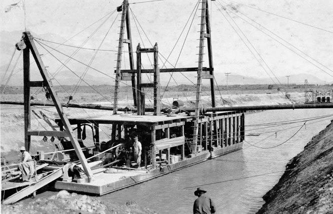
| (1908)^#^ - Dredge No 1 in 1908. The dredge got its power through electric lines running from nearby Cottonwood Power Plant. |
Historical Notes The electric-powered dredge was used to work on the 21-mile stretch of unlined Aqueduct, from the Intake across from Aberdeen to the Alabama Gates, north of Lone Pine. |
 |
|
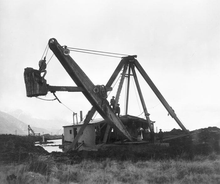
| (1911)* - Dipper dredge working in main canal, Owens Valley. |
 |
|
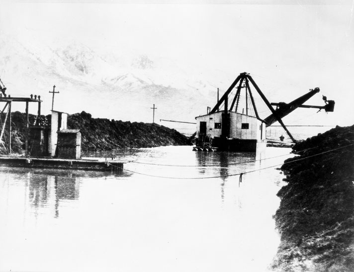
| (1911)* - Electric-powered dredge working in main canal, Owens Valley. |
 |
|
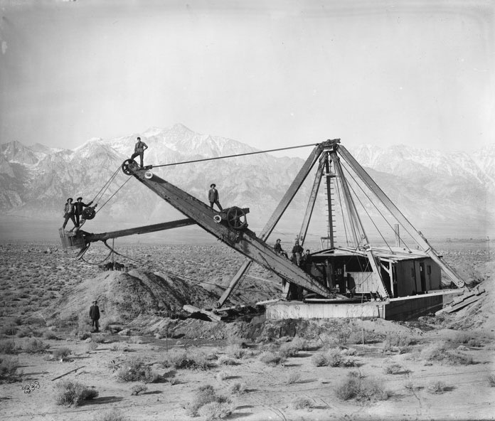
| (ca. 1910)* - The electric dredge displaced millions of cubic feet of earth in construction of the LA Aqueduct. |
 |
|
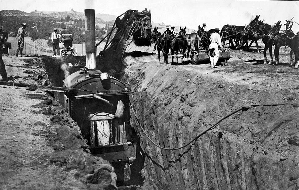
| (ca. 1911)*# - Men in steam shovels work in conjunction with mule teams during the excavation process. |
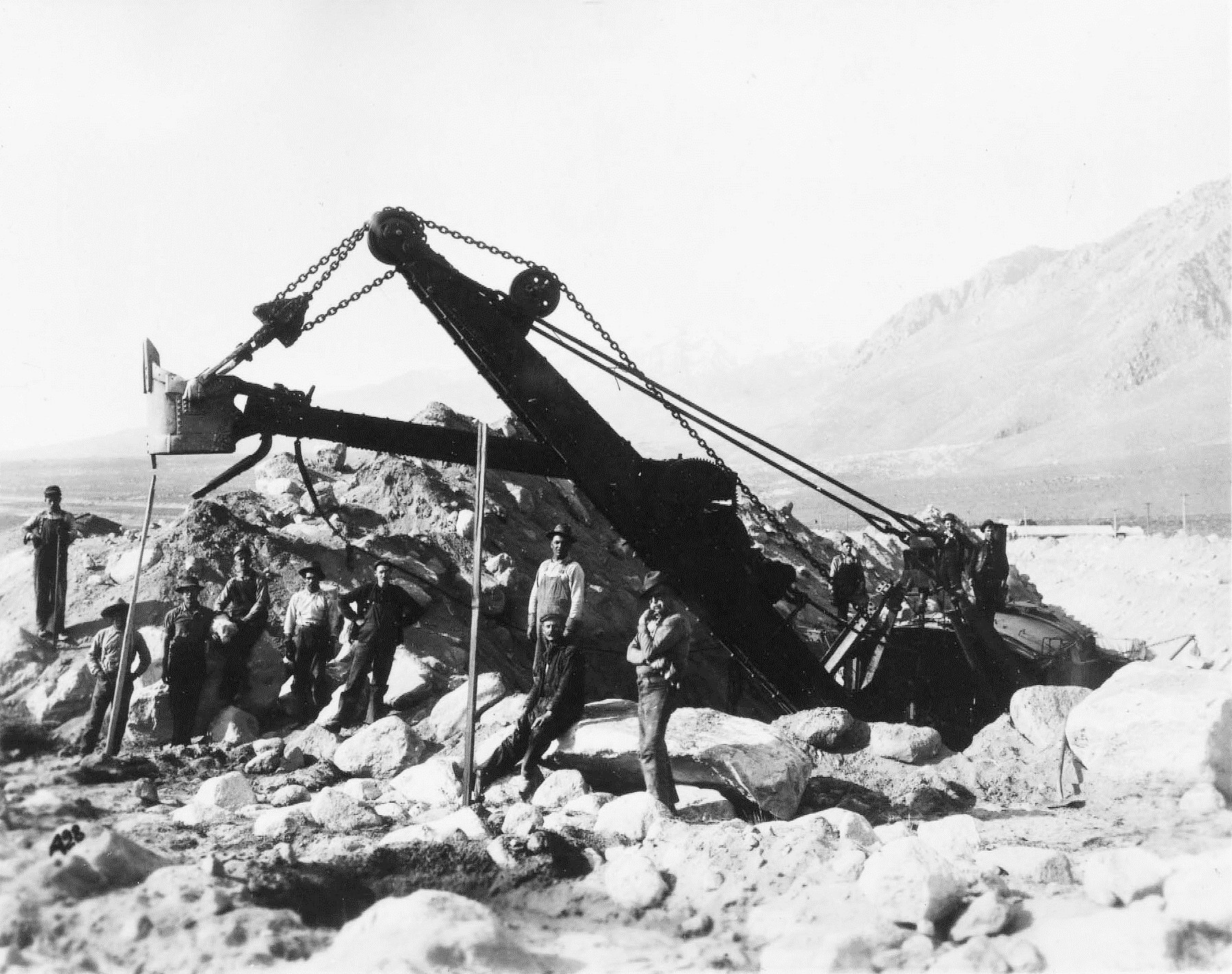 |
| (ca. 1912)* - Marion steam shovel excavating the open concrete-lined section of the Los Angeles Aqueduct in southern Owens Valley. |
 |
|
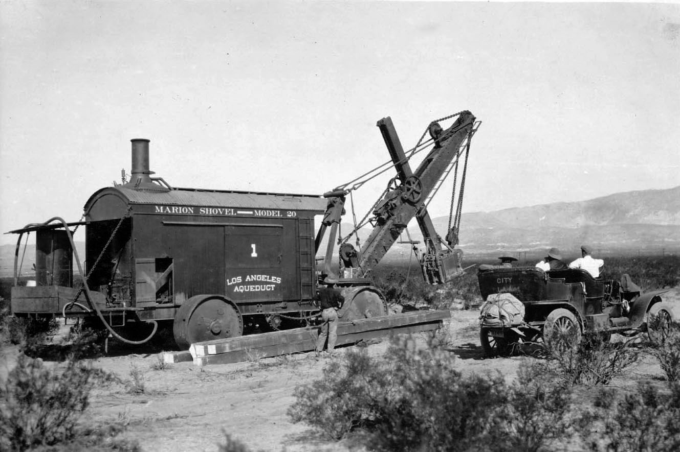
| (ca. 1912)^# - Close-up view of steam shovel No. 1 next to early model car. |
 |
|
| (ca. 1912)* - Labor crew by steam shovel No. 2 posing for the camera. |
* * * * * |
Steel Pipe, Siphons, and High-Pressure Sections |
Where the aqueduct crossed deep canyons and valleys, engineers relied on steel and reinforced concrete siphons to carry water under extreme pressure. These sections required massive pipe, precise engineering, and complex installation methods. From the Jawbone Siphon to the long steel runs across Antelope Valley, these high-pressure sections presented some of the most difficult construction challenges of the entire project. |
 |
|
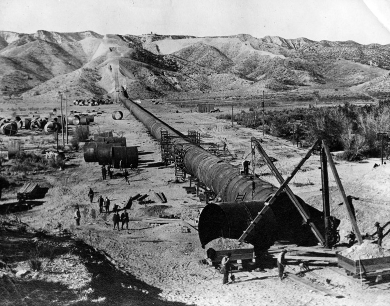
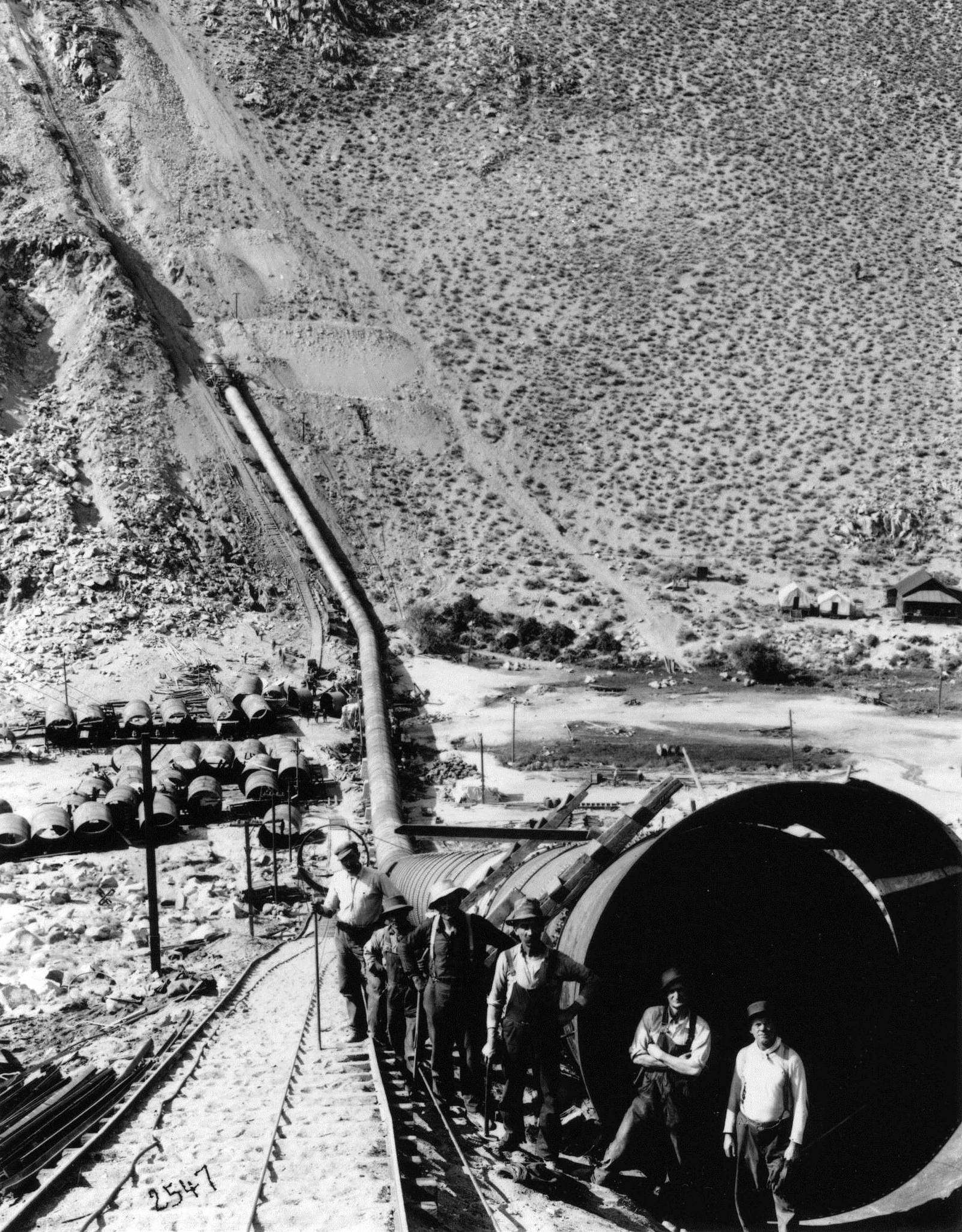
| (1910)*^# - Construction of the aqueduct pipe in the Mojave Desert. |
 |
|
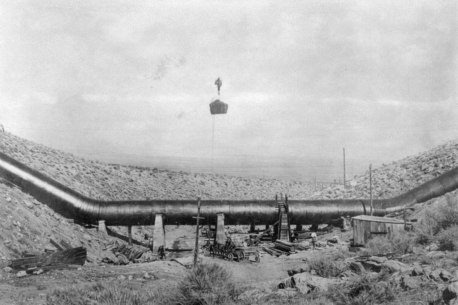
| (ca. 1912)* - Due to the extreme pressure caused by water running down the canyons, the sag pipes needed to be supported by huge concrete pillars. |
 |
|
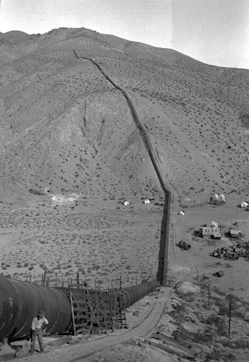
| (ca. 1912)* - View shows one of the methods used for hauling pipe sections up the steep canyons. |
 |
| (ca. 1912)* - A view of workmen posing in front of a new section of the aqueduct pipeline. |
 |
|
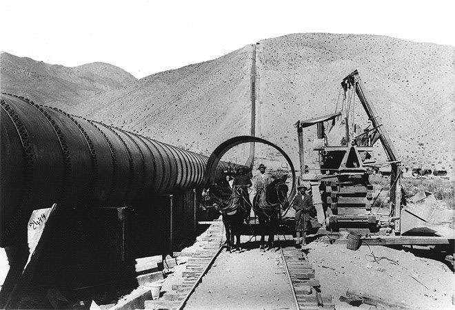
| (ca. 1912)* - Photo of a team of mules pulling a section of the aqueduct pipeline on a rail. |
 |
|
| (1912)* - Construction of the Jawbone Siphon section of the LA Aqueduct. |
Historical Notes The construction of 12 miles of steel siphon in the Aqueduct provided some of the greatest challenges. In a canyon 120 miles north of Los Angeles, the aqueduct’s engineers designed their most imposing work, an 8,095 foot steel pressure siphon across desolate Jawbone Canyon. |
 |
|
| (1912)* - The Jawbone Siphon begins to take shape. |
Historical Notes The spectacular Jawbone Siphon in the Mojave Desert, a giant roller coaster of a pipeline, was one of the toughest sections to build. Construction started in January 1912 and was completed in March 1913. |
 |
|
| (1913)* - View showing the Jawbone Siphon from north end. |
 |
|
| (1913)* - View of the almost completed pipeline in the Jawbone Siphon of the Los Angeles Aqueduct. |
Historical Notes The Jawbone Division of the LA Aqueduct begins at Red Rock Summit at an elevation of 3,320.00 feet and extends to the Pinto Hills at an elevation of 3,171.00 feet. The length is 119,795 feet, of which 60,657 feet is canal, 43,658 feet is in tunnel and 15,480 feet consists of flumes and siphons. The total fall consumed is 148.96 feet. |
 |
|
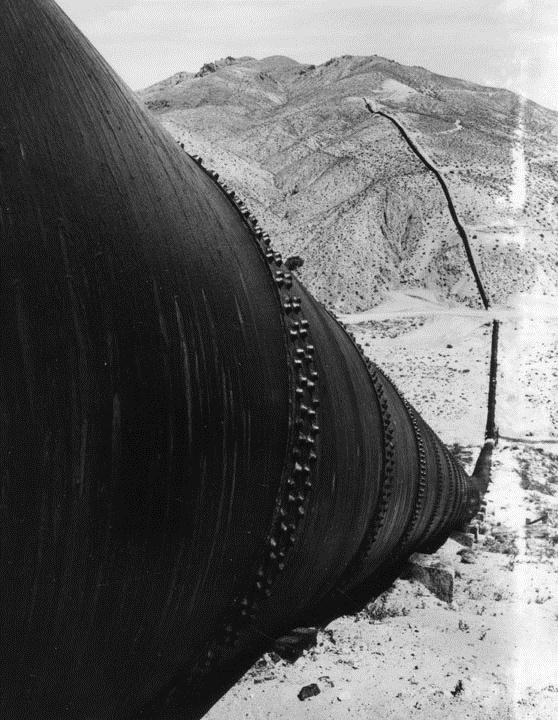
| (1913)* - View from near the top of the hill of the Jawbone Section. |
Historical Notes The Jawbone Sag Pipe was designed to handle 368 pounds per square inch of pressure at the bottom of the 1,000-foot deep canyon. |
 |
View showing one of the "sag pipes" of the Los Angeles Aqueduct in Jawbone Canyon. The aqueduct is based on gravity flow that does not require pumping or siphoning. Instead, water is conveyed via pressure developed in the down slope to force the water through the up slope. Jawbone Canyon is located just west of Highway 14, south of Randsburg Red Rock Road in Kern County. This section of the aqueduct, built in 1913, was designed by William Mulholland. |
|
| Jawbone Canyon Section of the Los Angeles Aqueduct |
 |
|
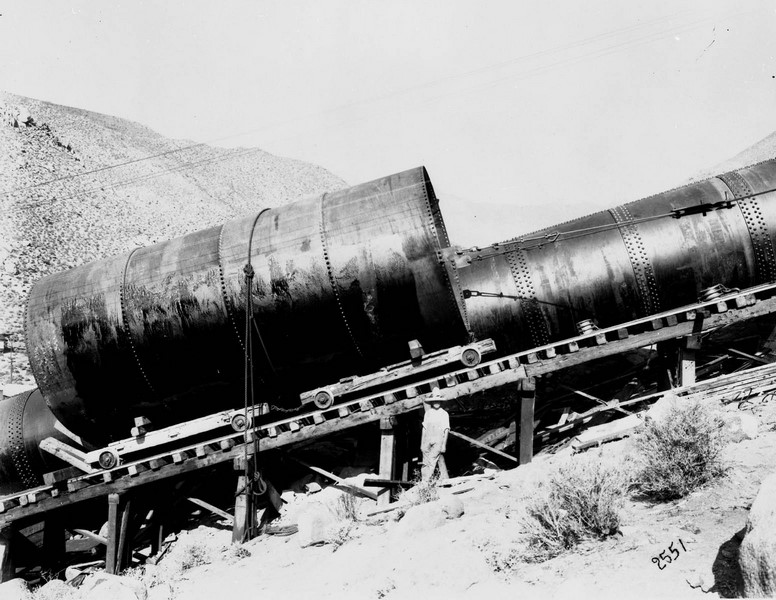
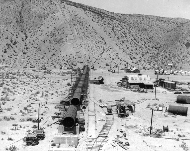
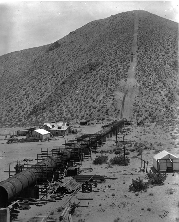
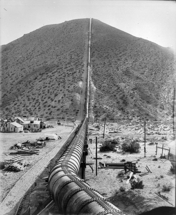
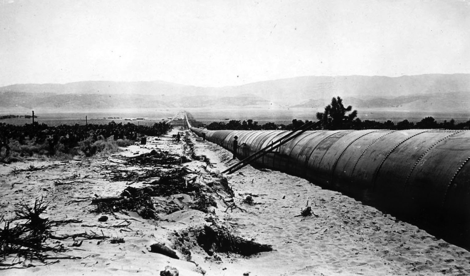
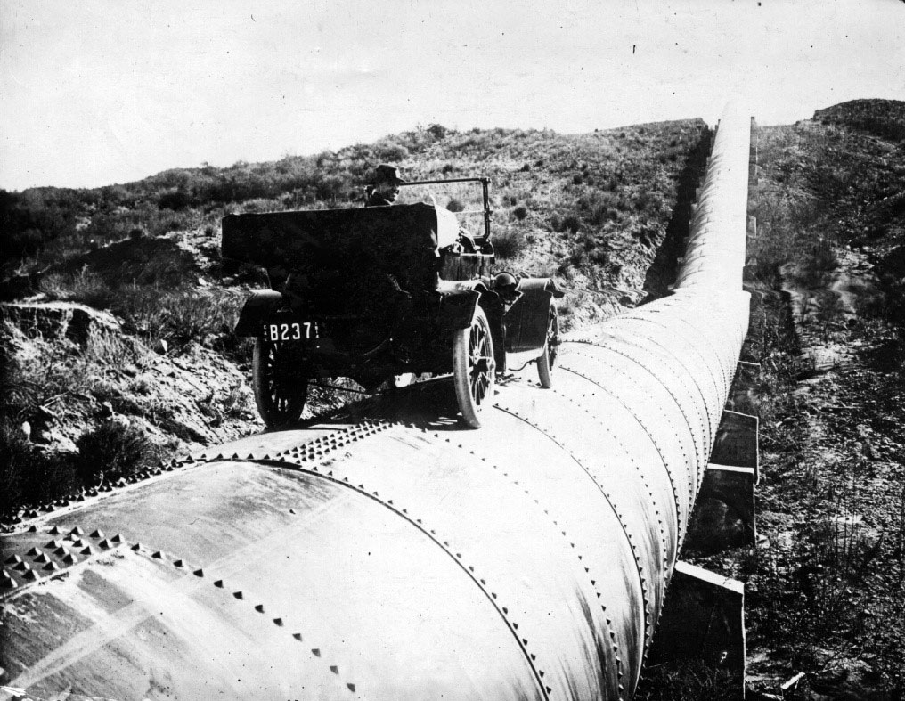
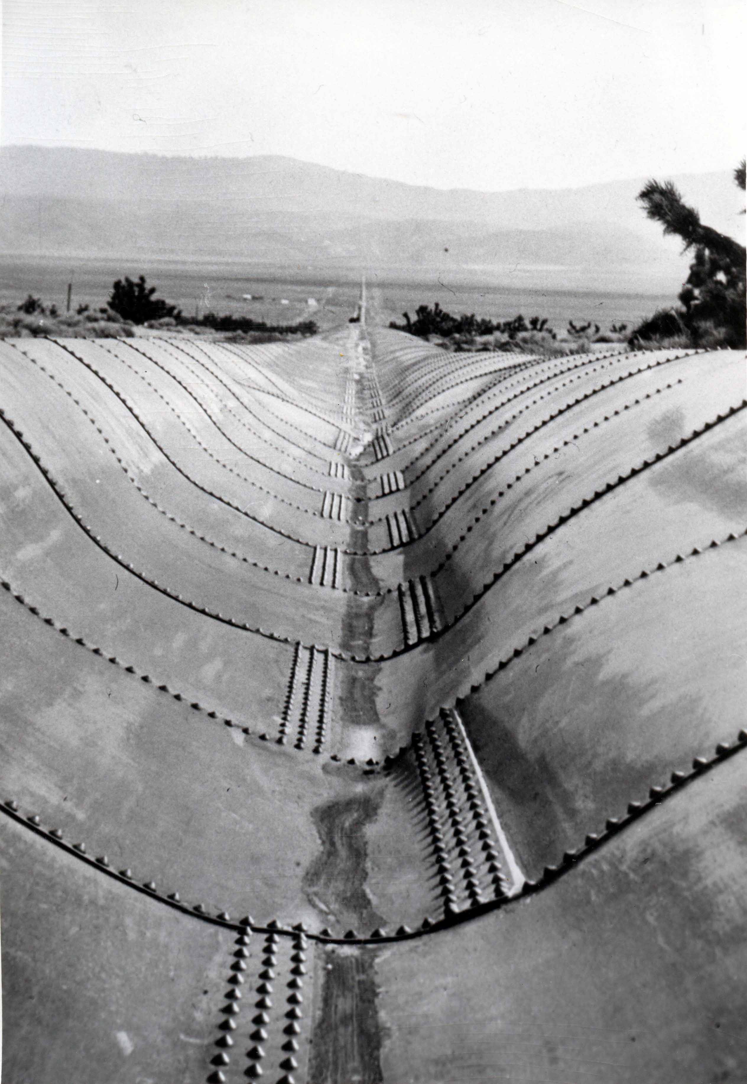
| (ca. 1913)^# - View showing the longest section of steel pipe along the aqueduct, running through Antelope Valley. |
Historical Notes The longest siphon on the aqueduct is the pipe crossing Antelope Valley. It is 21,767 feet in length, and up to heads of 80 feet is built of concrete, the remaining 14,497 feet being steel pipe. The concrete and steel pipes are both 10 feet in diameter. The maximum head on this siphon is 200 feet, and the weight of the steel is 3,511 tons. |
 |
|
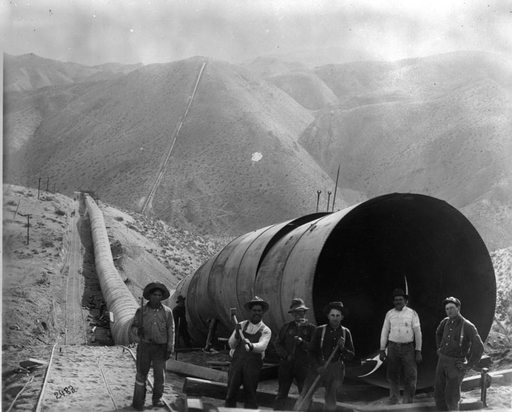
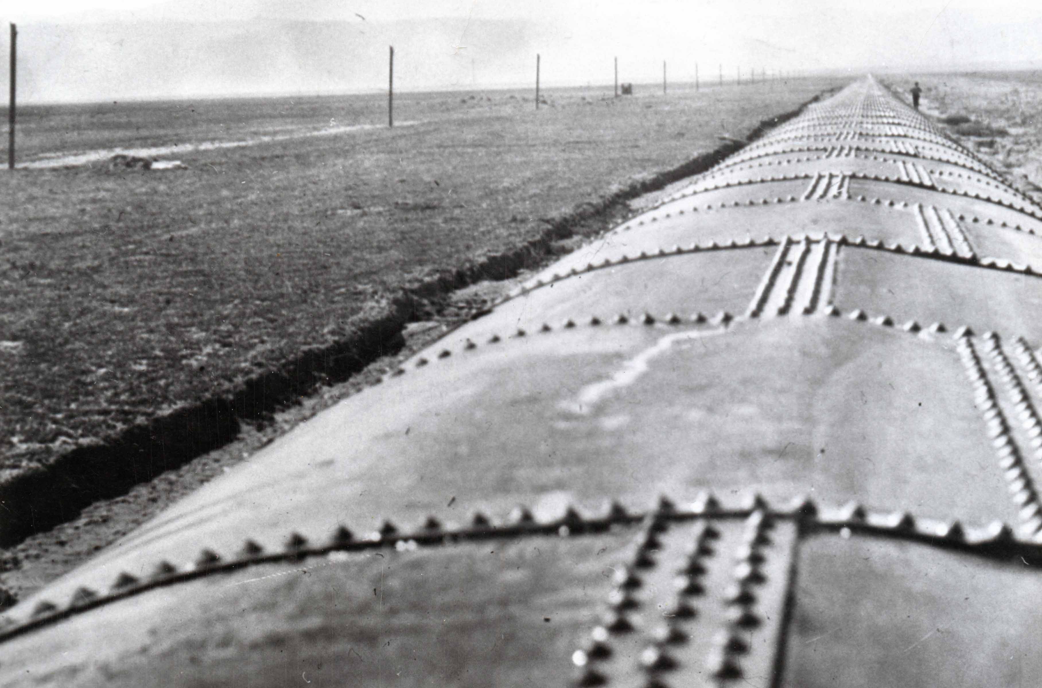
| (ca. 1913)*^ - Close-up view of the longest section of steel pipe along the aqueduct in Antelope Valley. |
* * * * * |
Whitney Siphon
 |
|
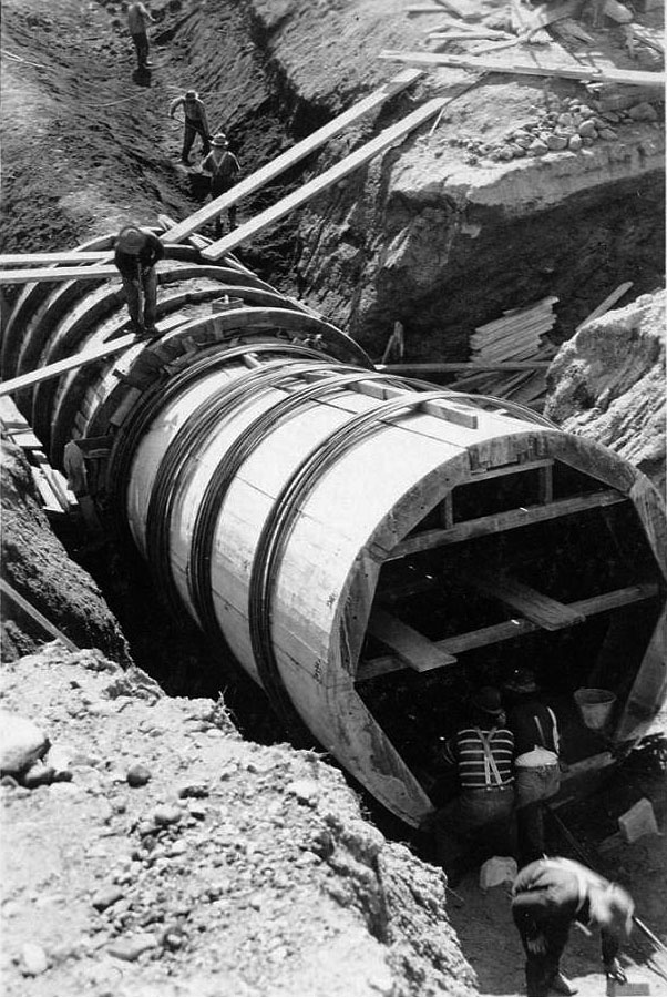
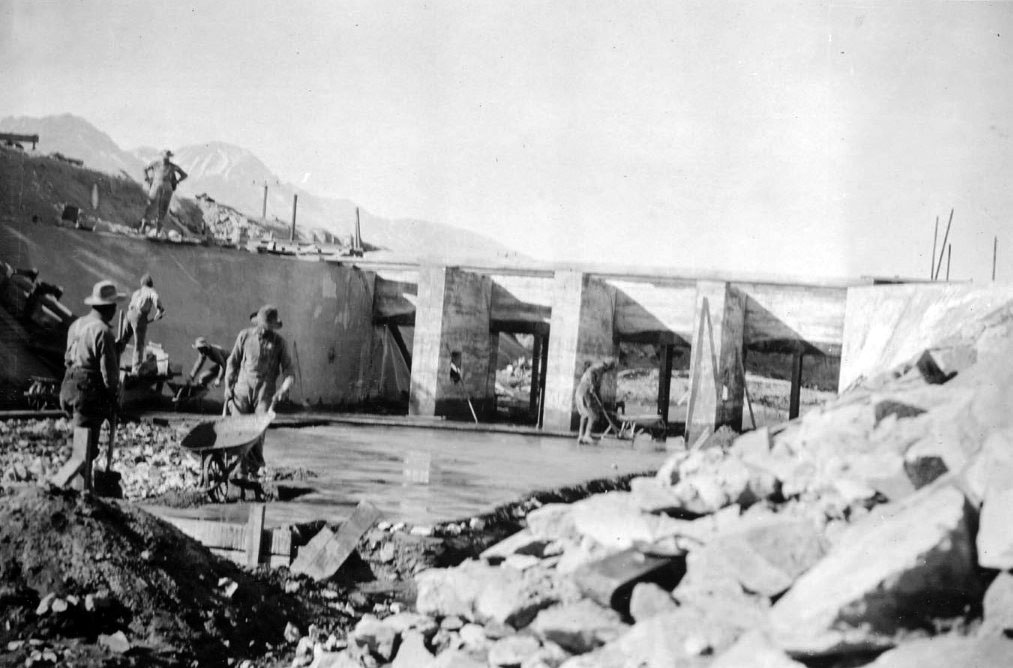
| (1909)^ – View showing Whitney siphon for the L.A. Aqueduct under construction. |
| Historical Notes
Whitney Canyon construction started in 1909. The section of the aqueduct through Whitney and Elsmere Canyons is noteworthy for its use of concrete in the siphon rather than the more usual riveted steel construction. |
 |
|
| (1909)^ – Close-up view showing construction of the Whitney siphon - Saugus Division. |
| Historical Notes
From the Sixth Annual Report of the Bureau of the Los Angeles Aqueduct (July 1911): The Whitney Siphon is a reinforced concrete pipe 10 feet in diameter, with an 8-in shell on the top and sides, and rests on a broad concrete base. The pipe was cast in position. The reinforcing steel consists of half-inch circular iron rods so spaced as to give a factor of safety of four on the steel. It is probable, however, that the concrete alone has sufficient strength to resist the bursting pressure, as the mixture was made very rich to obtain both water tightness and strength. Two expansion joints were put in this pipe. They are of the "Z" type and coated with asphalt paint. The only apparent leakage that has occurred at any place in the pipe is at one of these joints. In the Elsmere Siphon, which was built subsequently, no expansion joints were used. As far as known, in diameter these are the largest reinforced concrete pipes in the United States, but larger ones have been built in Spain. |
* * * * * |
Transport to Jawbone |
Getting massive steel pipe to the remote Jawbone Canyon site required extraordinary logistics, including railroad delivery, wagon transport, and the use of 52-mule teams to haul individual sections across desert terrain. |
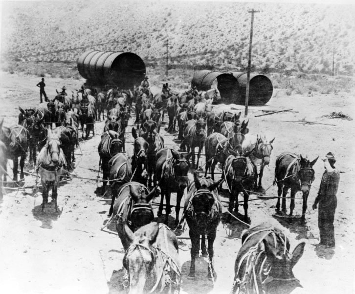 |
| (1912)* - 52-mule team hauling sections of aqueduct pipe to the Jawbone Siphon. |
Historical Notes Each 36-ton section of steel pipe was hauled 4 miles from Cinco to Jawbone Canyon by a team of 52 mules. |
.jpg) |
|
| (1912)*#* - A 52-mule team, six abreast at the wheel, transporting a 30-ton section of steel pipe during construction of the Jawbone Siphon. |
Historical Notes Most of the 15,000 tons of siphon steel needed for the aqueduct was transported by 52-animal teams driven by three freighters and two swampers. |
 |
|
| (1912)^#^ - 52 Mule Team hauling pipe for the Jawbone section of the Los Angeles Aqueduct in the Mojave Desert. |
* * * * * |
Scale & Completed Pipe |
Photographs in this group emphasize the immense size of the aqueduct’s steel pipe, using people, wagons, and automobiles for scale to convey the magnitude of the finished work. |
 |
|
| (ca. 1913)*^^ - A man is seen behind the wheel of an early model car sitting on top of a completed section of the LA Aqueduct. |
 |
|
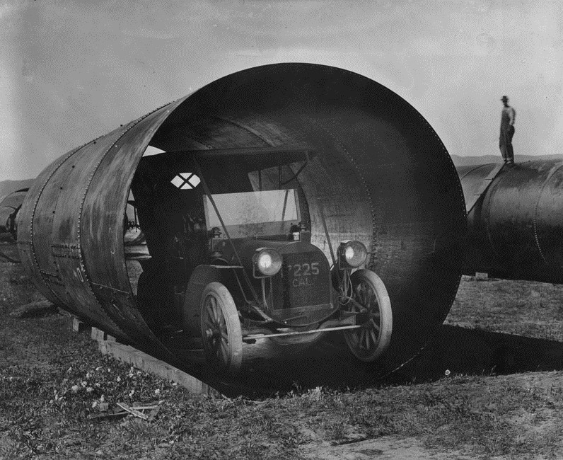
| (ca. 1913)* - An automobile fits into a section of siphon pipe used in the Los Angeles Aqueduct. |
Historical Notes The pipe was manufactured on the East Coast in 36-foot-long sections, each weighing more than 25 tons. The sections were transported by train to Cinco. From there, they were loaded onto huge wagons and carted the final four miles by teams of 52 mules. The town of Cinco was founded as a work camp in the early 1900s for workers on the Los Angeles Aqueduct. |
 |
|
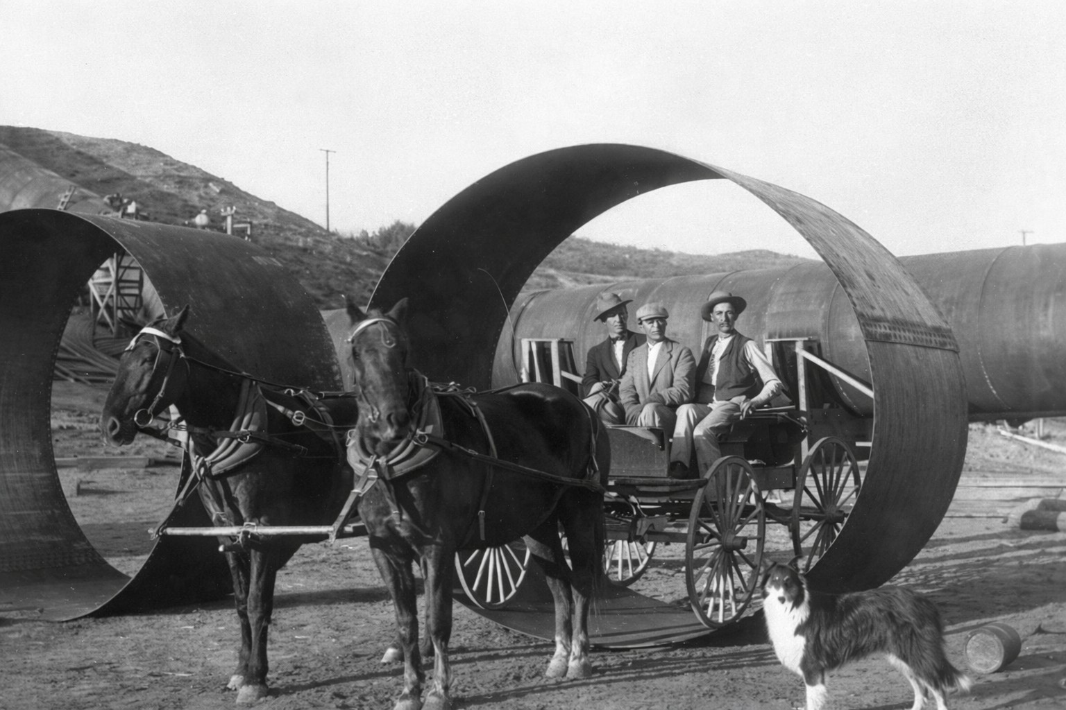
| (n.d.)* - To emphasize the size of the Aqueduct pipe, three men on a horse-drawn wagon are positioned within a pipe section. It appears the dog in the photo is also posing for the camera. |
* * * * * |
Fabrication & Preparation |
Before installation, aqueduct pipe sections were carefully prepared and riveted, a labor-intensive process that ensured strength, water tightness, and the ability to withstand high internal pressure. |
 |
|
| (n.d.)#* - Workers prepare aqueduct pipe. |
Historical Notes Approximately 191,785 rivets, varying in diameter from 5/8" to 1-1/4", were used in construction--each rivet weighs 5 pounds. |
* * * * * |
Storm Damage |
Shortly after the aqueduct opened, an intense 1914 storm in Antelope Valley severely damaged a section of steel siphon, providing an unexpected but revealing test of the system’s design and resilience. |
 |
|
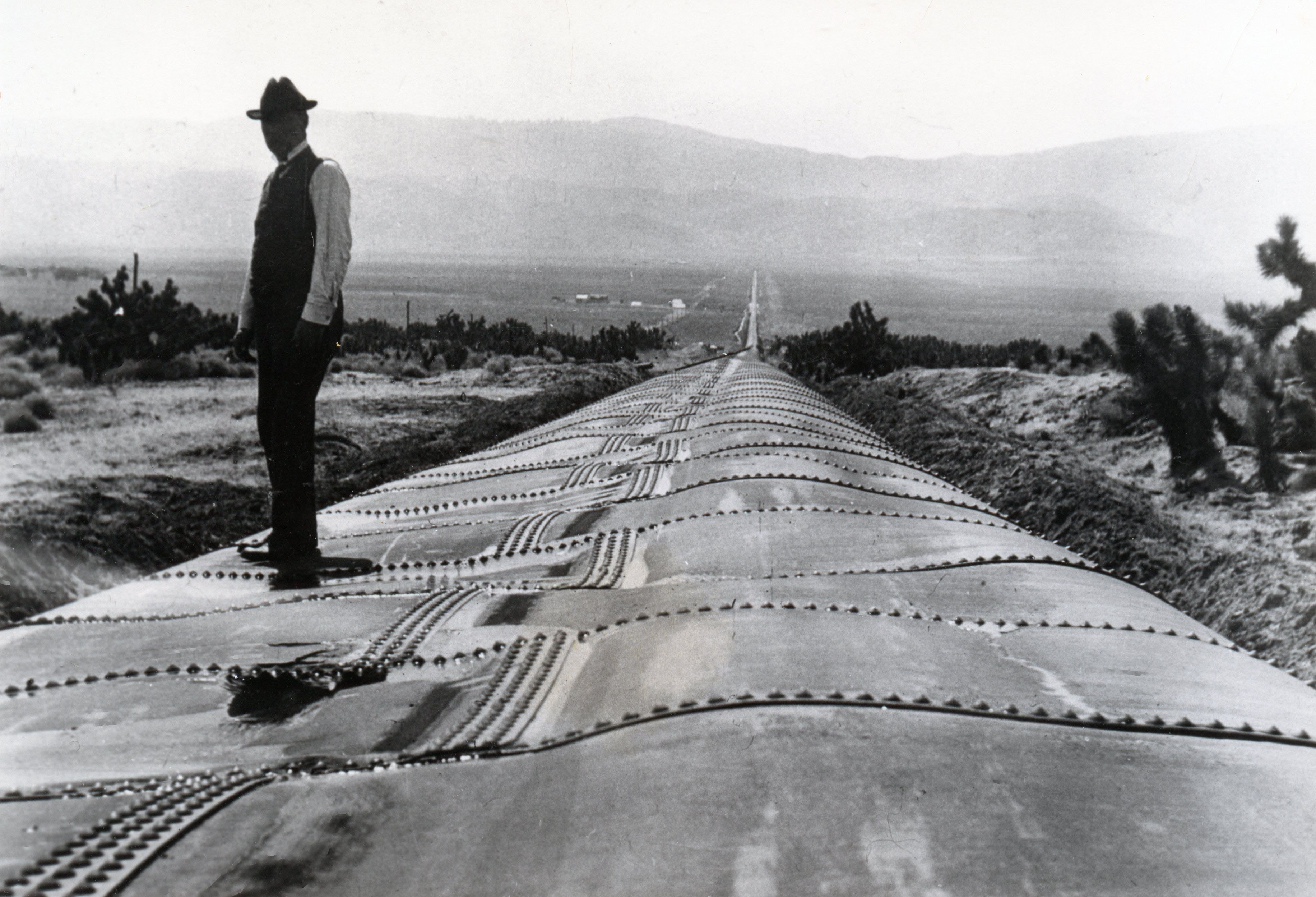
| (1914)*^ - View showing the damaged aqueduct pipeline through Antelope Valley resulting from a major 3-day storm in February, 1914 (3-months after the aqueduct's official opening). |
Historical Notes In February, 1914, the rainfall in the Mojave Desert region exceeded by nearly fifty per cent in three days the average annual precipitation. Where the steel siphon crosses Antelope Valley at the point of the greatest depression, an arroyo or run-off was indicated that fifteen feet was the extreme width of the flood stream, and the pipe was carried over the wash on concrete piers set just outside the high water lines. The February rain, however, was of the sort known as a cloud-burst, and the flood widened the wash to fifty feet, carried away the concrete piers, and the pipe sagged and broke at a circular seam. The steel pipe collapsed like an empty fire hose for nearly two miles of its length. In some places the top of the pipe was forced in by atmospheric pressure to within a few inches of the bottom. Many engineers pronounced the collapsed pipe a total loss, and advised that it be taken apart, the plates re-rolled and the siphon rebuilt. |
 |
|
| (1914)*^ – View showing William Mulholland standing on a section of the Antelope Siphon damaged by a major flood. Note: Water pressure alone would restore the pipe to its original circular form. |
Historical Notes The damage to the Antelope Siphon was repaired by the simple expedient of turning the water on after the break was mended, relying on the pressure to restore the pipe to circular form. The hydraulic pressure, under gradually increasing head, restored the pipe to its original shape without breaking any of the joints or shearing the rivets, and a month after the collapse the siphon was as good as new. The total cost of repairing the siphon was only $3,000. It would have cost about $250,000 to take it apart and rebuild it. |
* * * * * |
Testing the System and Turning on the Water |
Before the public dedication in November 1913, the Los Angeles Aqueduct had to be tested as a working system from end to end. Crews inspected gates, regulating works, and intake structures in Owens Valley, then carried out controlled releases to confirm flow, stability, and safety along the full route. This section documents those final preparations, including early gate operations, the first official release of water into the aqueduct, and the test runs at the San Fernando Valley cascades that set the stage for opening day. |
Owens Valley Gates and Intake
 |
|
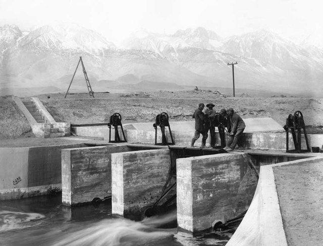
| (1912)^*# – View showing workers constructing the regulating gates at the main canal in Owens Valley. |
 |
|
| (1913)*#* - Workers raising the gates at the intake near Aberdeen in Owens Valley. |
Historical Notes On February 13, 1913, water was officially released into the aqueduct to flow south toward Los Angeles. |
* * * * * |
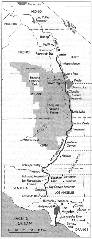
Map of the Los Angeles Aqueduct
(ca. 1908)**^ - Map showing the full extent of the 233 mile long Los Angeles Aqueduct running from its intake in Owens Valley to the point at which the water cascades down into the northeast San Fernando Valley.
|
 |
* * * * * |
Preparation for Opening Day
.jpg) |
|
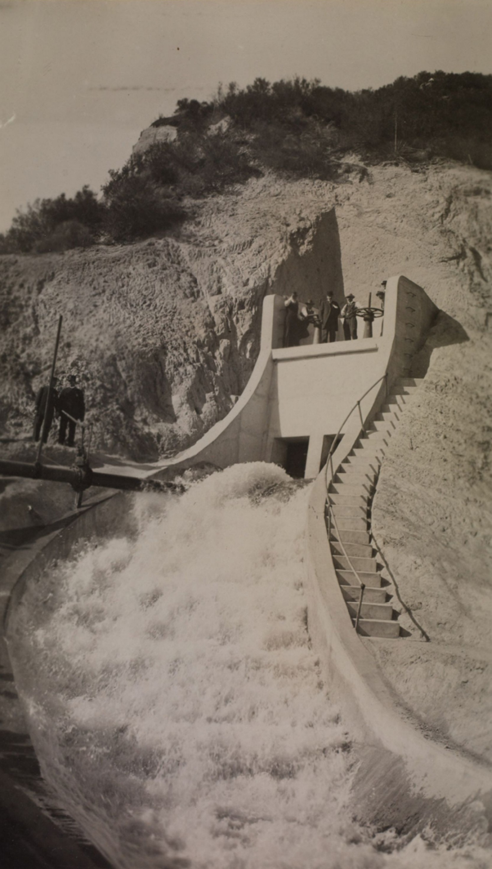
| (October 16, 1913)* - The gates are opened to allow water to cascade down above the San Fernando dam during a dual test and photo opportunity for the new Los Angeles Aqueduct before the opening ceremonies. |
* * * * * |
The Aqueduct Is Officially Dedicated |
After five years of continuous construction, water from the Owens Valley reached Los Angeles in November 1913. The completion of the aqueduct was marked by public tests, ceremonial gate openings, and a formal dedication at the San Fernando Valley cascades. Tens of thousands attended the event, witnessing the moment when the city’s new water supply first flowed south. This section documents the dedication ceremonies and the culmination of one of the most ambitious engineering projects in American history. |
 |
|
| (1913)* – Opening of the Los Angeles Aqueduct headwater gates at Sylmar during the November 5 dedication ceremony. Among those at the wheels was H. A. Van Norman, Owens Valley division engineer and namesake of today's Van Norman Reservoir. Others included Roderick Mackay (chief construction engineer), D. L. Reaburn (Saugus division engineer), A. C. Hansen (Jawbone Division engineer), and Adna R. Chaffee, Jr. (U.S. Army). Photo from the Ernest Marquez Collection. |
 |
|
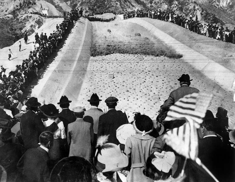
| (November 5, 1913)*# - Men, women, and children stand in awe as water is released from the gates at the top of the cascades. Many of the spectators are waving American flags. Wiliam Mulholland can be seen at right-center of photo just above the American flag. |
Historical Notes Over 30,000 Los Angeles residents came to the San Fernando Valley to see the opening ceremony of the Los Angeles Aqueduct, where the first water from the Owens Valley completed its journey to Los Angeles. William Mulholland presided over the ceremony and called out for the water gate to be opened with five of the most famous words in Los Angeles history: ''There it is, take it". |
 |
|
| (November 5, 1913)* - Crowds watch as the water gates are opened and the Los Angeles Aqueduct water starts to flow down the cascades into the San Fernando Valley. |
Construction of the LA Aqueduct Video
Click HERE to see a short (5 min.) video titled: 'The Great Los Angeles Aqueduct' |
 |
|
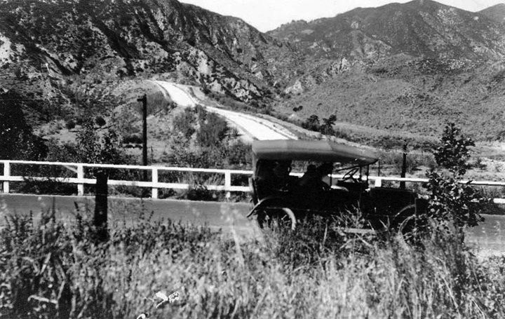
| (1915)* – An early model car traveling past the terminus of the Los Angeles Aqueduct in present day Sylmar just south of Newhall Pass in the San Fernando Valley. The aqueduct had been completed by William Mulholland two years earlier in November 1913. The road in photo is likely the predecessor to Highway 99 and Interstate 5 heading towards the Ridge Route between Los Angeles and Bakersfield which had just been completed the same year of 1915. |
 |
|
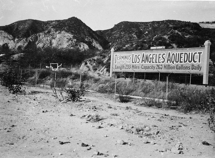
| (n.d.)^# - Terminus of the Los Angeles Aqueduct - This photograph shows a sign advertising the terminus of the Los Angeles Aqueduct, which had been completed in November, 1913. The sign was located near where present day Interstate 5 runs just east of the Van Norman Reservoir in Sylmar. In the background to the North are the San Gabriel Mountains, just east of the Newhall Pass. To the left of the sign can be seen the original water cascade that marked the terminus of the Aqueduct. The sign states "Terminus of the Los Angeles Aqueduct. Length 233 Miles. Capacity 260 Million Gallons Daily". |
 |
|
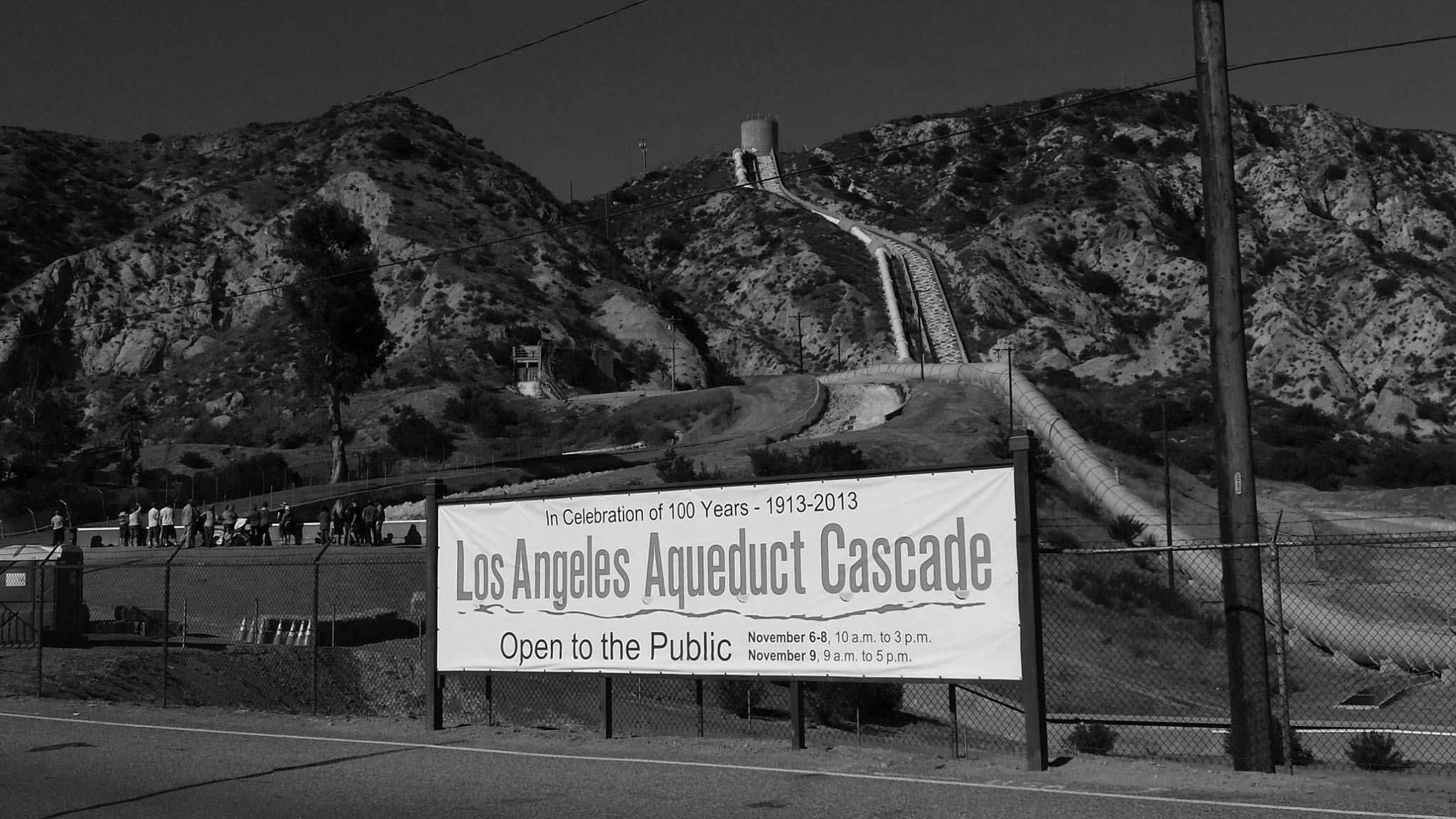
| (2013)^** - View showing visitors at the foot of the original Los Angeles Aqueduct Cascade on its 100 year anniversary (left). The cascade for the Second Los Angeles Aqueduct (completed in 1970) is on the right. |
 |
|
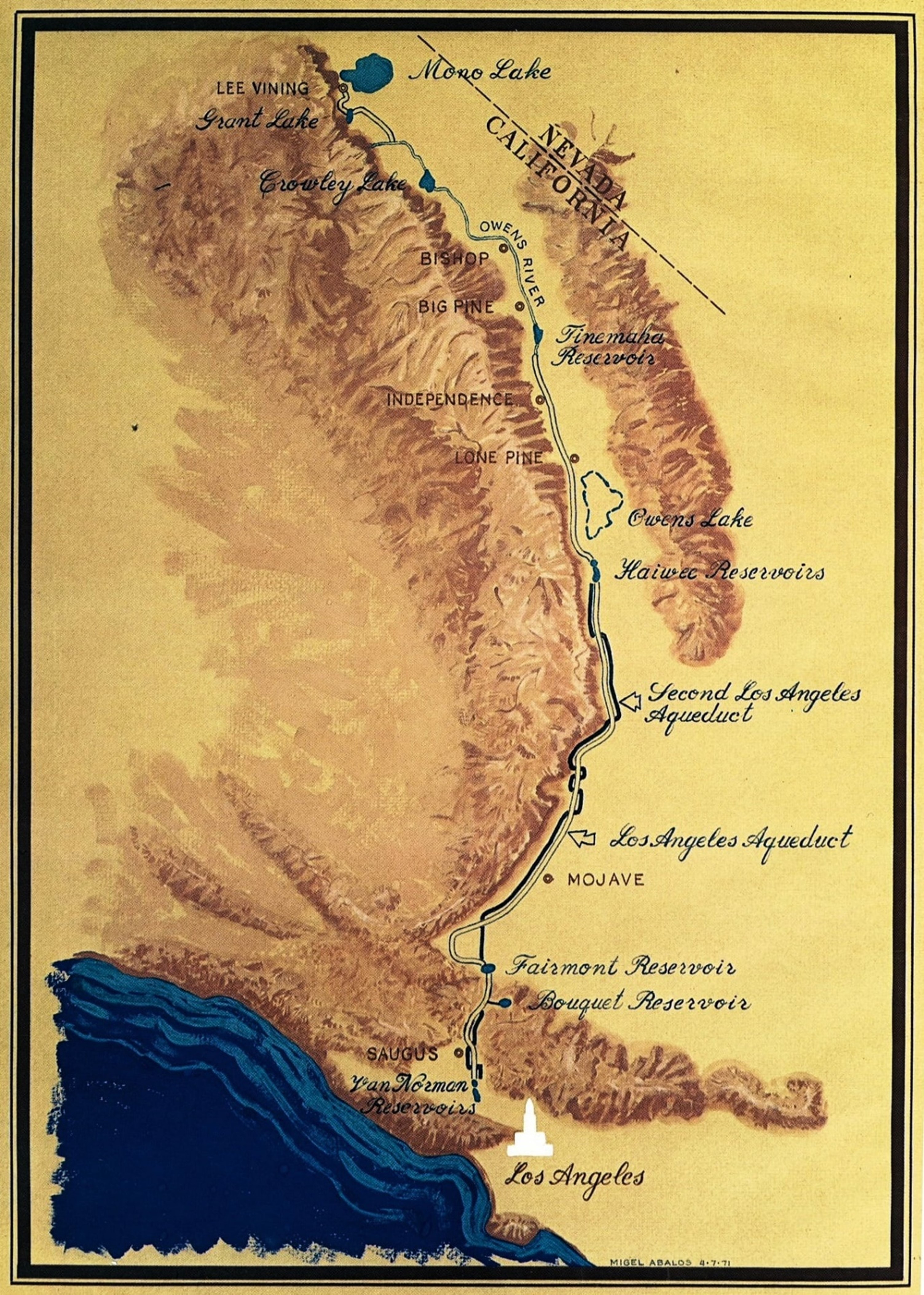
| (1971)* - Schematic map of the Los Angeles Aqueduct by Migel Abalos. |
 |
|
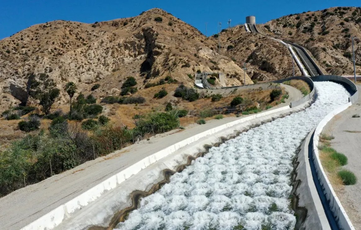
| (2022)* - Water flows down the Original Los Angeles Aqueduct cascade (left) at Sylmar, while the Second Aqueduct cascade (right), with its surge tank and penstock pipe above, remains dry. This contrast highlights the system’s flexibility—when hydroelectric plants are running, most water bypasses the cascades and flows through the penstocks for power generation and reservoir delivery. Photo by Dean Musgrove, Los Angeles Daily News/SCNG). |
Historical Notes In typical operation, the hydroelectric plants handle the full volume of incoming water, so most or all water bypasses the cascades and flows through the penstocks for power generation. This is the most frequent condition, making water flowing down the cascades an occasional event rather than a daily occurrence. The cascades thus serve as an overflow channel, ensuring operational flexibility and system safety during rare periods of maintenance, repairs, or unusually high water flow. Click HERE to see more on the Second Los Angeles Aqueduct. |
Historical Background Video (w/Catherine Mulholland)
Click HERE to see a short (4 min.) video on the Construction of the Los Angeles Aqueduct |
Los Angeles Aqueduct History and Photos |
* * * * * |
History of Water and Electricity in Los Angeles
More Historical Early Views
Newest Additions
Early LA Buildings and City Views
* * * * * |
References and Credits
* DWP - LA Public Library Image Archive
^ YouTube - Construction of the Owens Valley Project
^^LADWP Publication: The Story of the Los Angeles Aqueduct
^*Santa Clarita Valley History in Pictures (Photo Credit - Alan Pollack)
^#OwensValleyHistory.com: Terminus of the L.A. Aqueductt; Antelope Valley; Cement Mill; Steam Shovel No. 1
*#Skyscraperage.com - LA Times: June 18, 1911 LA Aqueduct
**#California State Library Image Archive
^*#Calisphere: University of California Image Archive
^#^Construction Photos of Joseph Barlow Lippincott
^^*L.A. Aqueduct Centennial 2013
*#*Virtual Transportation Museum
*^^A History of the San Fernando Valley: lahistoryarchive.org
^^^California Museum: Today in CA History
*^*Wikipedia: Cowley County Historical Museum - Caterpillar Tractor Photo; Monolith, CA
**^William Mulholland and the Rise of Los Angeles by Catherine Mulholland
< Back