Early Power Substations and Switching Stations
IntroductionBehind every light switch in Los Angeles stands a vast and largely unseen network of receiving stations, switching stations, and converter facilities that make reliable electric service possible. These installations form the critical link between distant generating plants and the neighborhoods, industries, and businesses they serve.Beginning in the 1910s, the Los Angeles Bureau of Power and Light built a system of high voltage receiving and switching stations that allowed power generated along the Aqueduct — and later at Hoover Dam — to be delivered safely and efficiently into the growing city. Massive transformer banks stepped down transmission voltages for distribution. Switching stations divided long transmission lines into controllable sections, improving reliability and preventing widespread outages.By the 1930s, Los Angeles engineers were constructing some of the most advanced high voltage facilities in the world. The Boulder transmission line stretched 266 miles across the desert. Giant circuit breakers, synchronous condensers, and the world’s largest transformers were installed to manage unprecedented levels of power. In 1936, the entire municipal system was converted from 50 to 60 cycles in order to accept Hoover Dam generation — a monumental technical achievement.In later decades, the system expanded again with the construction of the Sylmar Converter Station, the southern terminus of the Pacific DC Intertie, allowing Los Angeles to exchange large blocks of power with the Pacific Northwest.The stations shown in this section represent more than electrical equipment. They illustrate how Los Angeles engineered reliability, independence, and growth through infrastructure built at a scale few cities in the world attempted. |
* * * * * |
Olive Switching Station (1917) |
 |
|
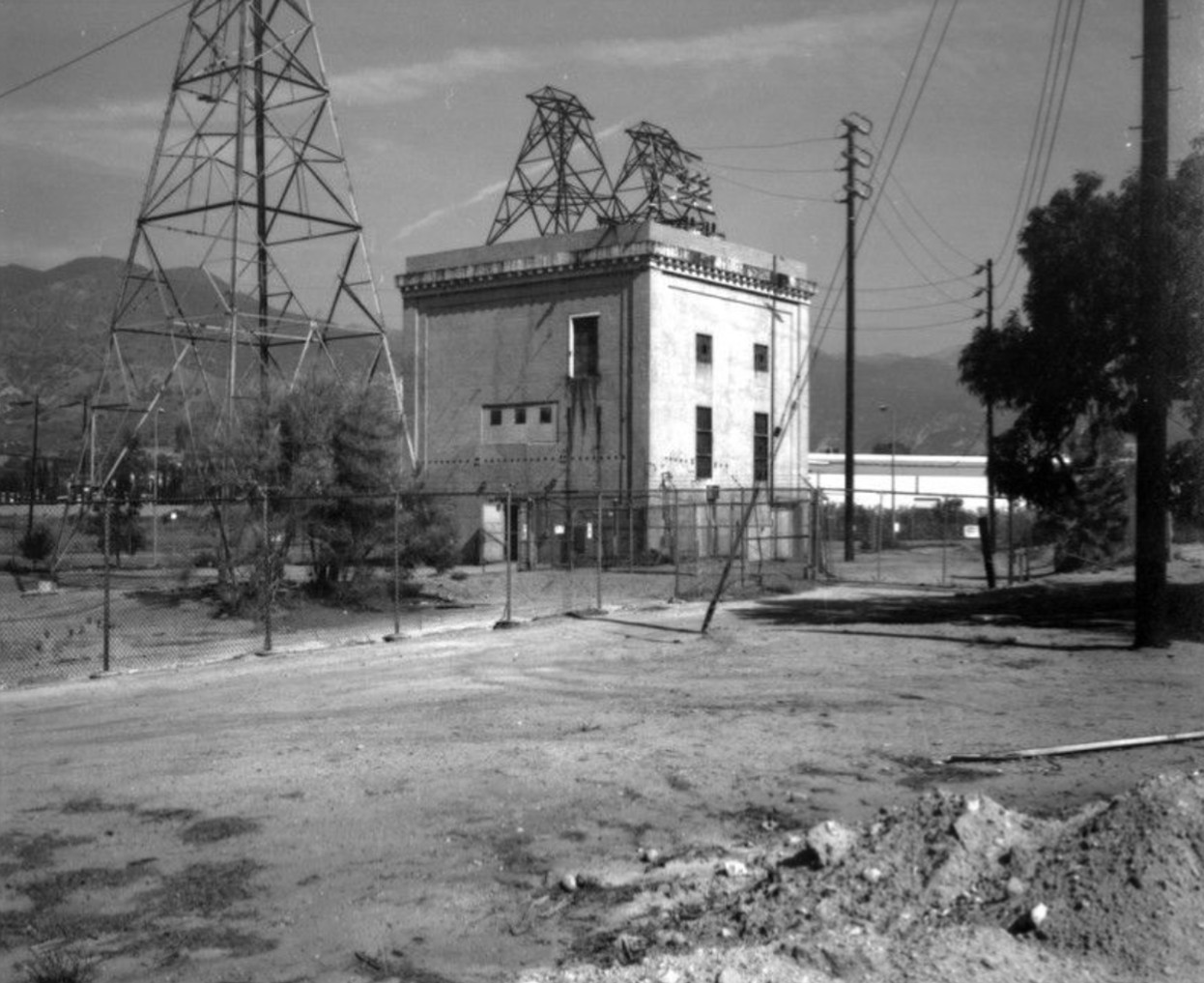
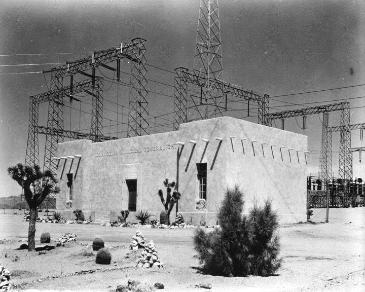
| (1917)* - Exterior view of Olive Switching Station, one of the first in Southern California. |
Historical Notes On March 18, 1917 the San Francisquito Power Plant No. 1, Unit 1 was placed in service and energy was delivered to Los Angeles over a newly constructed 115 kV transmission line. The 200 kilowatts generated by Unit 1 were the first commercial kilowatts generated by the Los Angeles Bureau of Power and Light. The Olive Switching Station was constructed between 1916 and 1917 at the mid-point of the 115 kV transmission line from San Francisquito Power Plant No. 1 to the central receiving station in the city (now Receiving Station A). Its main purpose is to ensure the reliability of the system by allowing a section of any circuit on which trouble develops to be cut out without affecting service. |
Olive View Switching Station (3 views)
 |
 |
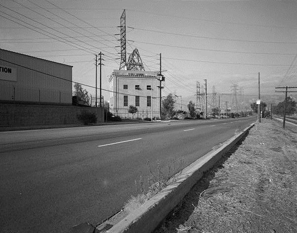 |
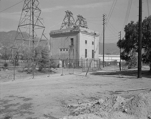
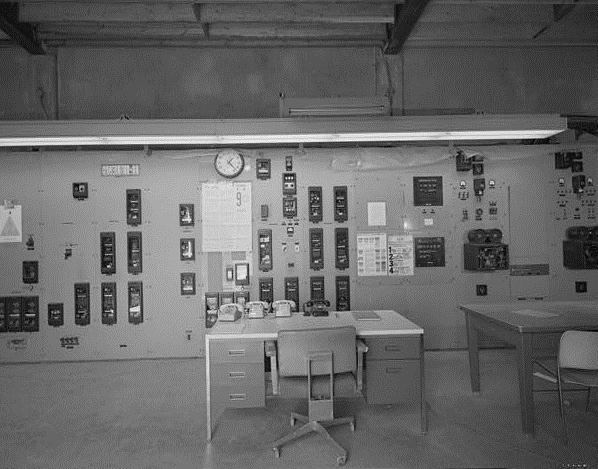
| South Corner View | Control Panel Room | Northeast View |
 |
|
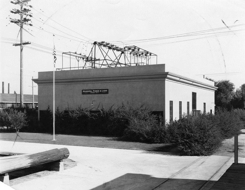
| (1929)* - Exterior view of Municipal Power & Light Station No. 2, a substation in Van Nuys. |
* * * * * |
Victorville Switching Station |
 |
|
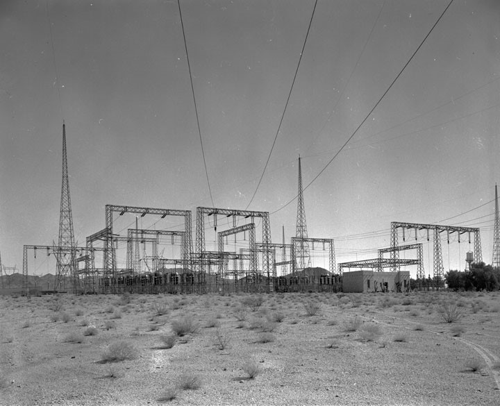
| (1936)* – View of the Victorville Switching Station. |
From the LADWP Historic Archive October 1936 – Two of the world’s most modern switching stations, each costing approximately $1,000,000, divide the Boulder transmission line into three equal parts. Both are of the outdoor type and located at Victorville and Silver Lake in the desert section of the line route. Because of the unusual length of the line, 266 miles, the stations are of vital necessity in assuring the utmost in continuity of service. |
 |
|
| (1930s)* - Victorville Switching Station - Electrical equipment - never sleeping sentinels which guard the 266- mile Boulder transmission line are these giant circuit breakers, largest ever built at the time, that are an integral part of the Victorville Switching Station. |
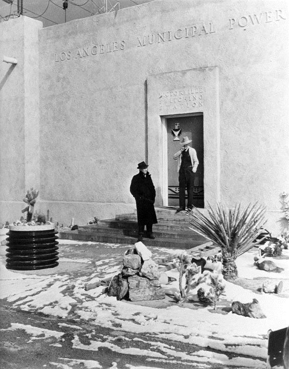 |
(1930s)* - Entrance to the Bureau of Power and Light's Victorville Switching Station after a snow storm.
|
* * * * * |
Silver Lake Switching Station |
 |
|
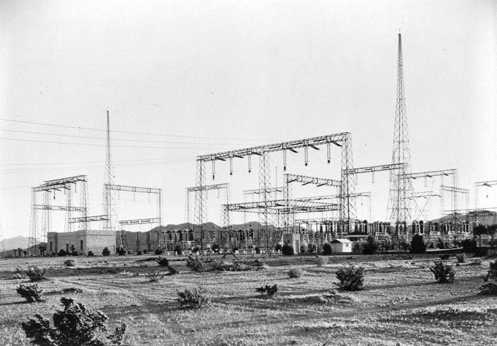
| (1930s)* - Bureau of Power and Light Silver Lake Switching Station. |
 |
|
| (1930s)* - Control house of the Silver Lake Switching Station - Bureau of Power and Light*. |
Historical Notes * In 1937 the Bureau of Power and Light consolidated with the Bureau of Water Works and Supply and became the Los Angeles Department of Water and Power (DWP). This coincided with the completion of Hoover Dam. Los Angeles got its first electricity from Hoover Dam on October 9, 1936. Click HERE to see DWP Name Change Chronology (1902 to present). |
* * * * * |
DWP Receiving Stations |
There are 23 receiving stations in the DWP system. Most of them are designated by a letter in the alphabet, reflecting the sequence in which they were built, and most also have a name, usually derived from a nearby street. Each receiving station has racks and rows of high voltage equipment in a yard larger than a few city blocks, and usually a control house facing the street, designed to reflect the architectural styles and aspirations of the time it was built. |
* * * * * |
Receiving Station B |
 |
|
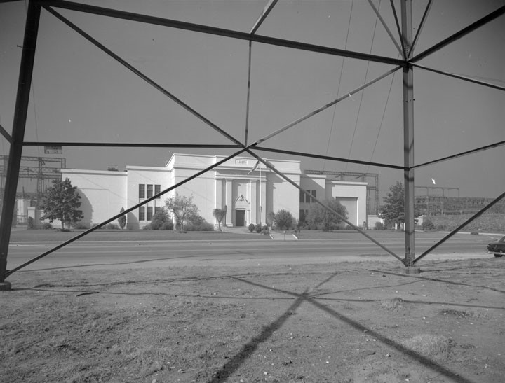
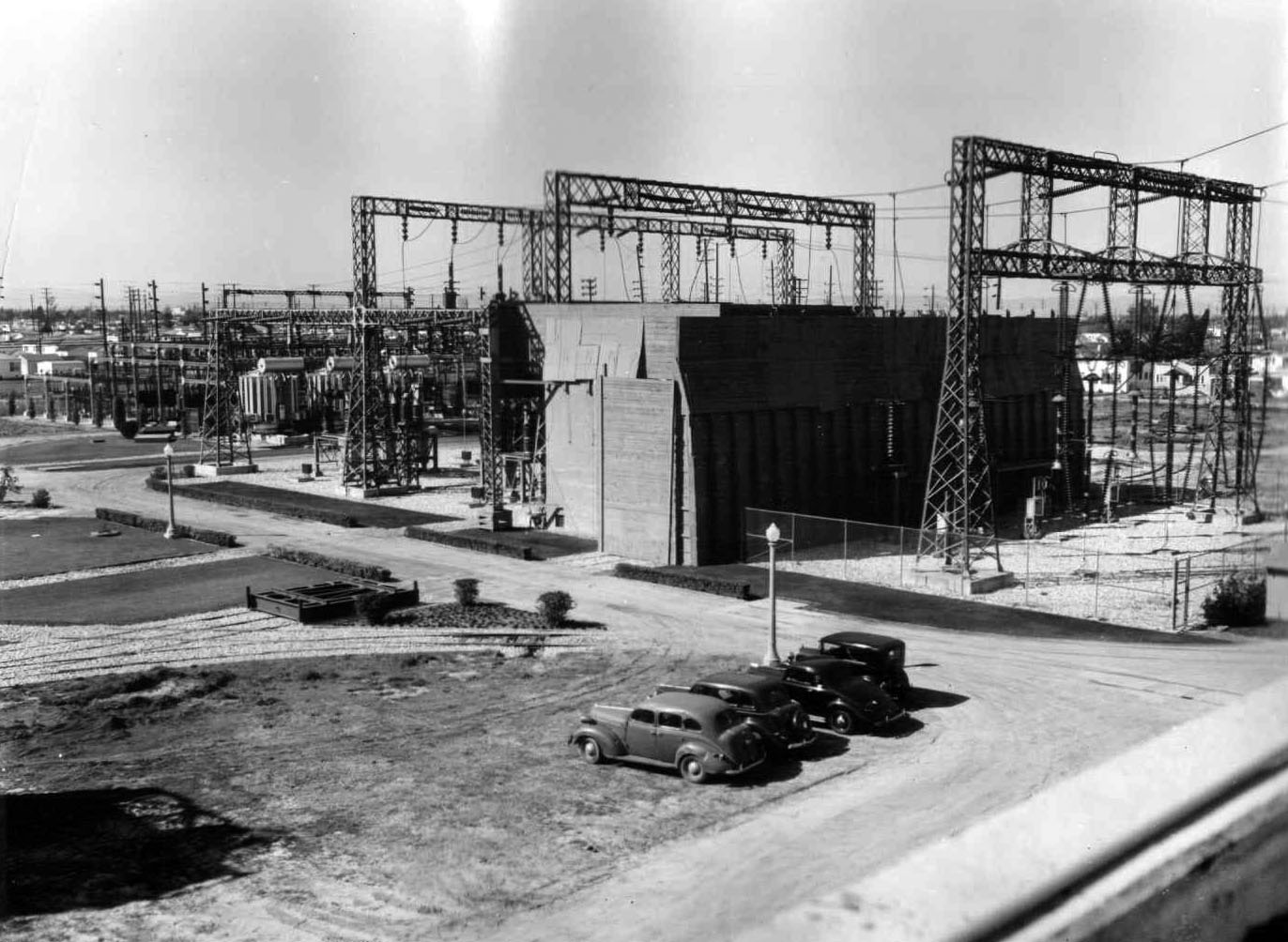
| (1927)* - View through a transmission line tower of Receiving Station B located at 9615 S. Central Ave. |
From the LADWP Historic Archive November 1927, to meet the needs of thousands of heavy industrial plants in the southeast and Harbor districts of the City, the Municipal Bureau of Power and Light placed in full operation, on October 12th, 1927 two new receiving power stations, involving an investment of $2,250,000. The first of the new power stations is situated at 95th Street and Central Ave; the second in Wilmington in the Harbor District. These stations it was explained by Chief Electrical Engineer E. F. Scattergood, of the Power Bureau, will serve as the first large units of a gigantic high voltage electric belt line which, when completed, will entirely encircle Los Angeles, and is now under construction by the Bureau. Approximately 300,000 horsepower of electric current, or enough energy to duplicate the work of 2,400,000 men, can be handled and distributed to industrial and domestic consumers through the new stations which are designated as Receiving Stations B and C. Prior to the completion of the new receiving stations, the Bureau received all of its power generated along the Aqueduct it its Central Station A on North Main Street. With the new stations in operation, energy is supplied to the Southwest industrial district and the Harbor zone directly from the Aqueduct transmission lines and by the lines of the private power company from whom the City purchases a portion of its electricity. Designed to be capable ultimately of handling 320,000 horsepower of electric energy each, the stations are now operating with a capacity of approximately 150,000 horsepower each, it was explained by Power Bureau engineers. Station B in the Southeast section of the city, it was stated, involved an investment of $1,500,000 while Station C, with a portion of its machinery still housed in temporary structures, cost $750,000. With the new receiving stations in operation, Mr. Scattergood pointed out, the Municipal Power Bureau is able more economically and efficiently to carry large volumes of electric power to the very heart of heavy consuming areas. These stations receive electric energy raised to a voltage varying from 132,000 volts to 33,000 volts. After passing through the huge stations the energy is reduced to those lower voltages required by factories, stores and homes. The high voltage belt line, of which the new stations are the first units to be completed, will carry high voltage energy by means of cables on tall steel towers in a great circle around the city of Los Angeles. from this electric belt line, which serves the same purpose as a railroad belt line, energy will be taken off at regular points and, after being reduced to the proper voltages, relayed to consumers. Use of such a high voltage belt line, it was pointed out by engineers, will eliminate the necessity of having hundreds of lower voltage pole lines running along the streets in practically every section of the city. The belt line and Receiving Stations also will insure greater reliability of service and will efficient method of conveying large blocks of electric power to the large consuming districts, engineers explained. |
 |
|
| (1936)* - World’s largest circuit breakers shown being assembled at Receiving Station B for reception of Boulder Dam power. |
* * * * * |
Substation Elements |
 |
|
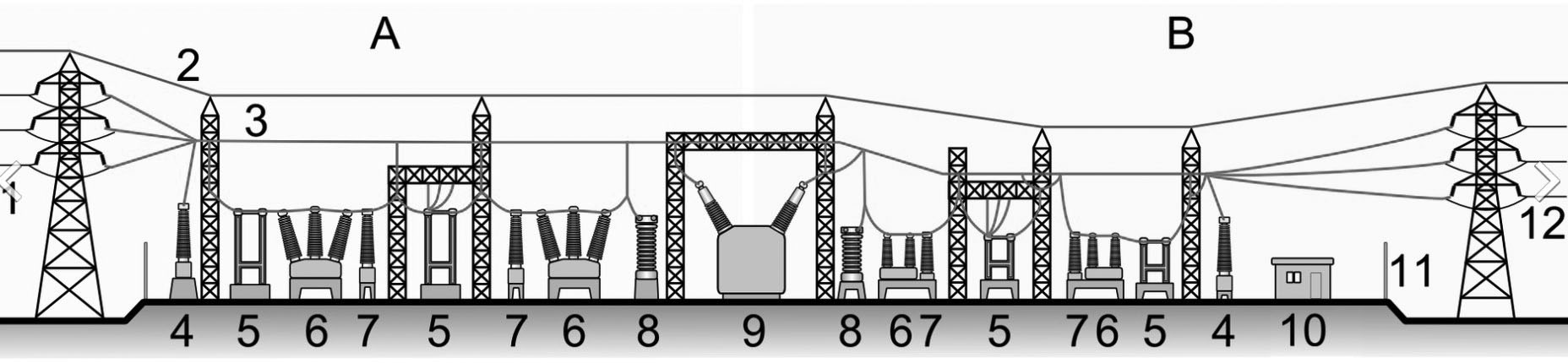
| Electrical Substation Model |
Elements of a Substation |
* * * * * |
Station Transformer and Equipment |
 |
|
| (1935)* - Huge 30 ton crane successfully undergoing test at Main Street Yards. Note the crane operator just visible in control box in upper right corner. Capable of hoisting a dead load of 30 tons, one of two new cranes for the Power Bureau’s transformer warehouse at 1630 North Main Street is now in active service. The crane will be able to handle the larger transformers to be used in The Bureau's new substations. |
 |
|
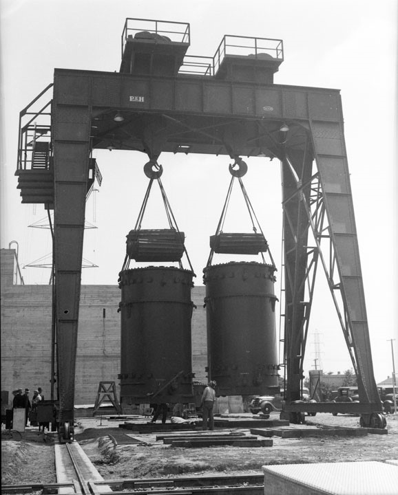
| (1936)* – Close-up view showing testing of the new Gantry Crane at Receiving Station B. |
From the LADWP Historic Archive Constructed for the express purpose of moving the immense auto transformers which constitute the receiving end of the 275,000 volt Boulder Canyon transmission line, a giant 150 ton Gantry crane now is ready for its acceptance tests at Receiving Station “B”. instead of being constructed with a stationary frame-work and traveling bridge, as is the case with the crane equipment at Station “A”, the four legs of the Gantry crane are mounted on wheels so that the entire unit may be moved the entire length of the crane track. Towering to an overall height of 53 feet, the unit has a vertical lift of 40 feet. It weights 100 tons, which is less than half of its lifting capacity. Although rated at 150 tons, the crane can lift an overload of 25 per cent with its two huge hooks. The span from rail to rail is 35 feet. The crane cost, including erection, was $33,285, according to Carl D. Udell who was in charge of preparing the specifications for the hoisting unit. It will be powered by two 40 horsepower and one 30 horsepower electric motors. Because of the tremendous weight of the crane when loaded to capacity, special care was used in the structural design of the 173 foot long runway on which the crane travels. According to V. Lankovsky, who supervised the preparation of plans, the runway was designed to sustain a load of 300 tons. In constructing the runway, a shallow trench was excavated to a depth of four feet. Thirty-foot piles then were driven into the ground at intervals of three feet. They were capped with concrete and upon this base reinforced concrete beams 30 inches wide and 48 inches deep were poured to form the support upon which the crane rails were to rest. Nine tie beams, 16 inches square, form rigid cross bracing support. At one end of the track a transformer pit is being constructed. It will be 21 feet square and 16 feet deep, sufficiently large to accommodate any one of the auto transformers. Walls are 6 inches thick and fully reinforced with steel. The pit will be capped with a waterproof, removable cover. |
| (1936)* - Moving a 50-ton transformer from 1630 N. Main Street to Receiving Station C in Wilmington. |
 |
|
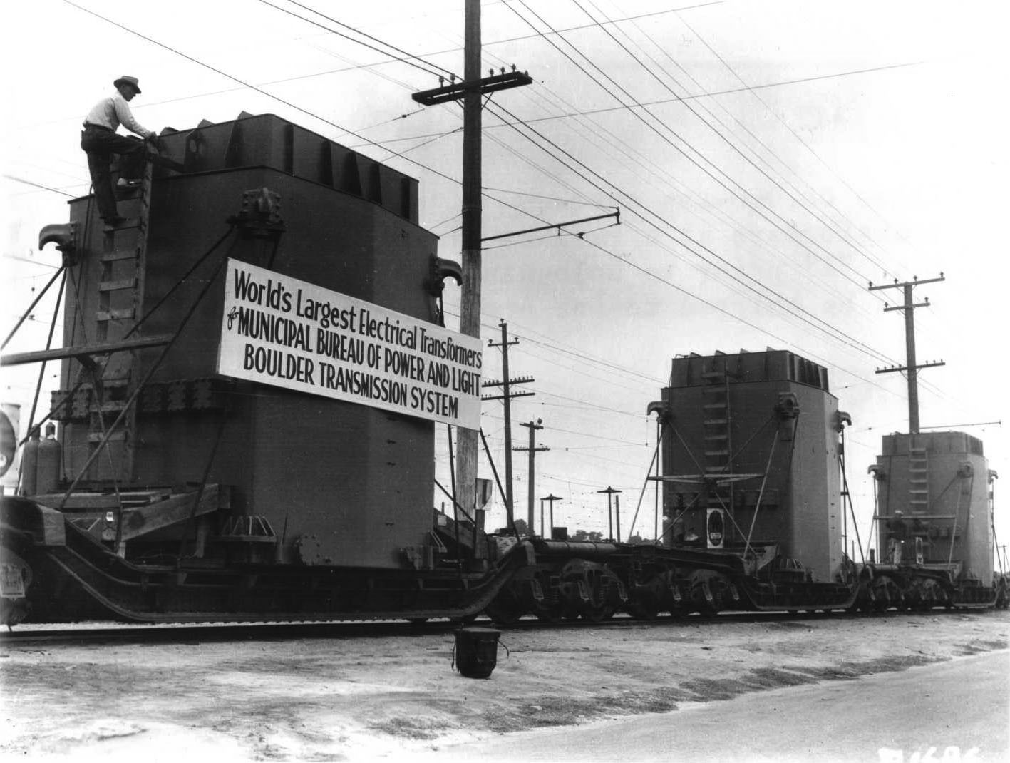
| (1936)^^ - View showing three of the boulder line transformers on heavy duty flat cars awaiting unloading. |
Historical Notes Large sign on transmorfer reads: World's Largest Electrical Tansfomers for MUNICIPAL BUREAU OF POWER AND LIGHT - BOULDER TRANSMISSION SYSTEM" Click HERE to see more in Early Power Transmission. |
 |
|
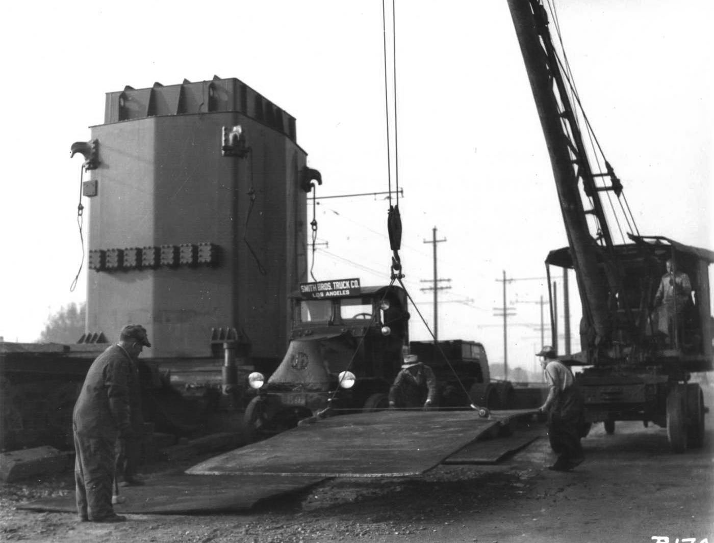
| (1936)^^ - View showing the unloading of one of the transformers. |
| (1936)* - Assembling a 186-ton transformer at Receiving Station B for Boulder Canyon transmission line. |
| (1936)* - Closer view showing one of seven huge 155-ton transformers being assembled at Receiving Station B – 9615 South Central Ave., for Boulder Canyon Project. |
 |
|
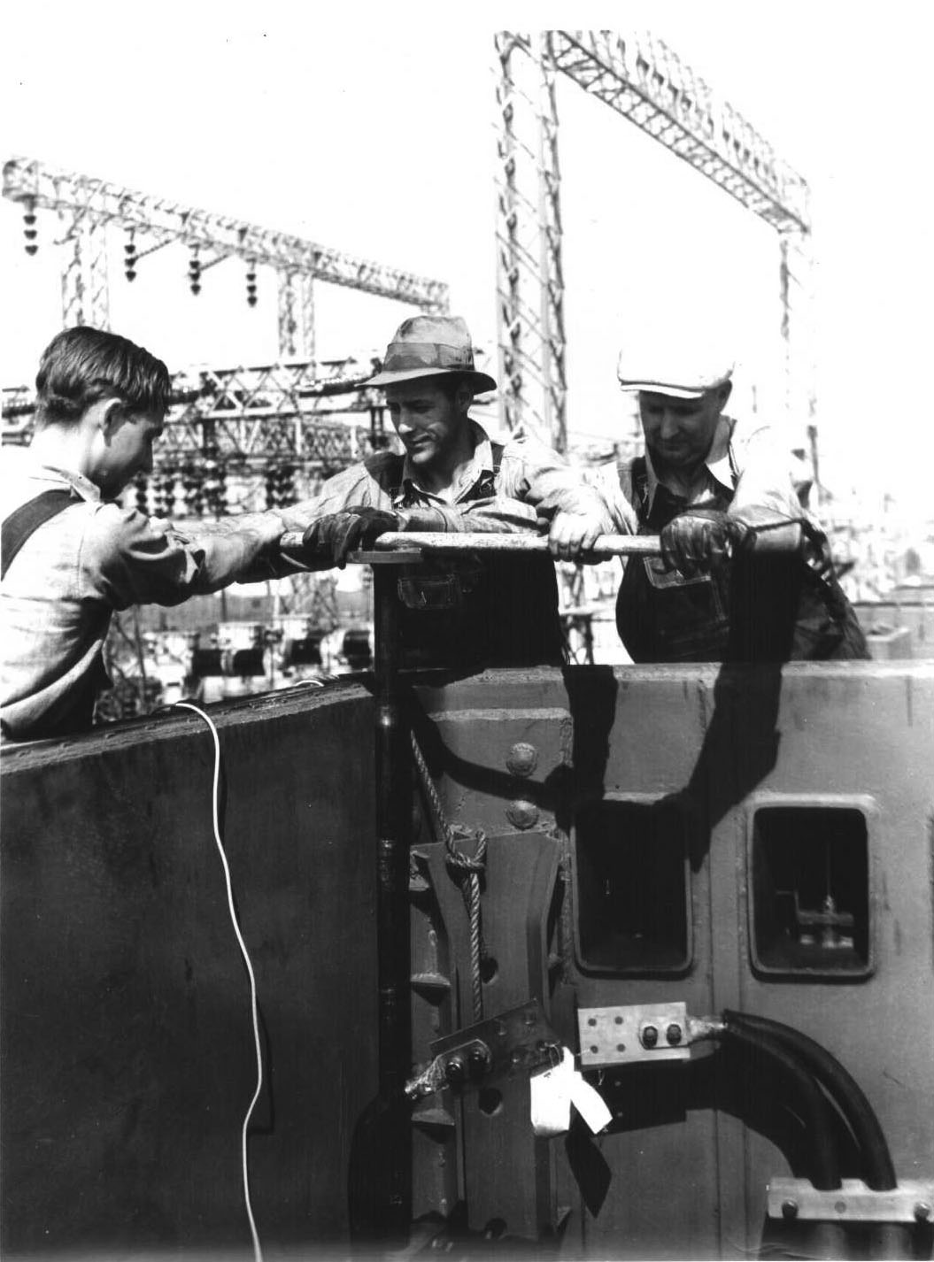
| (1936)^^ - Close-up view showing three workers assembling one of the large transformers. |
| (1936)* - Assembling 186-ton Boulder Canyon transmission line transformer at receiving station B workmen are shown attaching huge cooling fins to the body of a transformer - a total of 14 of these are required for each transformer. |
| (1936)* - 186-ton Boulder Canyon transmission line transformer at Receiving Station B. |
LADWP Historic Archive October 1936 – Terminus of the Boulder transmission line is Receiving Station ‘B’ located at 96th Street and Central Ave. As Boulder power enters the six huge 186-ton transformers, shown below, it starts through the first of several voltage “step-downs” before reaching Power Bureau consumers. |
| (ca. 1936)* - At the time these were the world’s largest transformers. They were installed at Receiving Station B for the Boulder Canyon Transmission Line. |
Historical Notes Six of these 186-ton transformers were required for proper operation of 266-mile transmission line. In 1936, they constituted the largest installation in the world, both from the standpoints of size and capacity. Each occupied a ground space of 11 ½ ft. x 23 ½ ft. and towered 36 ft. into the air. Each transformer and appurtenant equipment weighed approximately 170 tons, consisting in part of seven tons of copper, 47 tons of electrical sheet steel, nine tons of insulating material, 53 tons of coil and 15,000 gallons of transformer oil. |
 |
|
| (1936)* - Boulder Canyon transmission line circuit breakers installation at Receiving Station B. |
Historical Notes At the time these were the world's largest insulators. |
 |
|
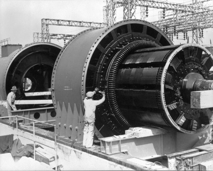
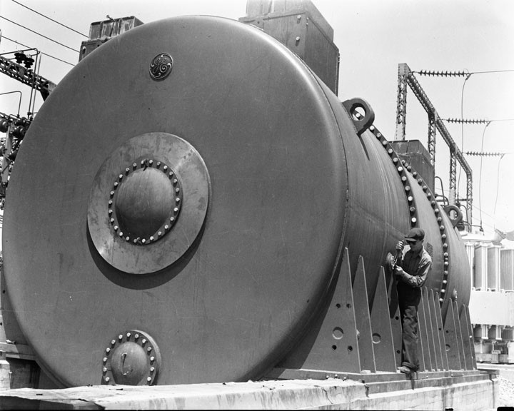
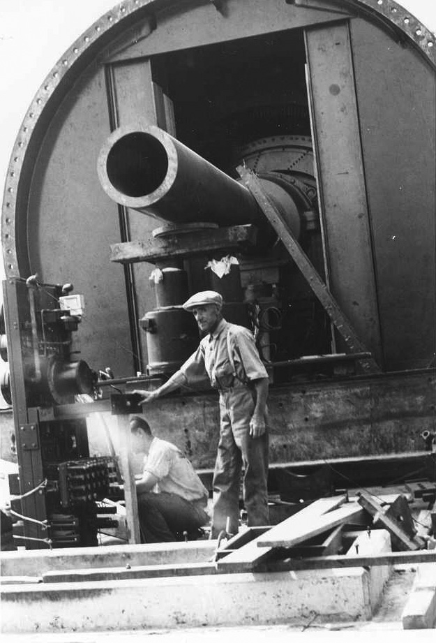
| (1936)* - Assembling the giant stator and rotor units of the condenser. Their combined weight is 165 tons. When in operation, the condenser will control the voltage and power factor of the Boulder Canyon Transmission System. |
LADWP Historic Archive The synchronous condenser units control the power factor and voltage of the transmission line. When erected on its reinforced concrete foundation at Receiving Station “B” the condenser will measure approximately 28 feet in length and 15 feet in diameter. Designed for outdoor use, operating parts will be enclosed so that the unit will resemble an enormous tank lying on its side. Foundation walls enclose a pit under the machine which will house auxiliary equipment such as the motor generator excitor sets. |
 |
|
| (1936)* - Synchronous condenser installation at Receiving Station ‘B’. |
LADWP Historic Archive Data supplied by J. P. Stratford who was in charge of preparing the specifications from which the condenser was fabricated, rates the capacity of the machine from 60,000 kva leading to 30,000 kva lagging power factor, thus permitting a total range of 90,000 kva. Operating voltage is 13,200 at 60 cycles. Contract price of each machine was $250,000 exclusive of installation costs. By controlling the voltage and power factor of the transmission line, the condensers provide an important link in assuring the highest possible efficiency in line operation. |
 |
|
| (ca. 1936)^^ - J. A. Griffitts opening the circuit breaker on the last DWP 50 cycle circuit. Taken in the old control house at RS-C in Wilmington. |
Historical Notes Prior to 1936, the Southland was sort of an electrical enclave. Both Edison and Los Angeles Bureau of Power and Light generated and distributed their power at 50hz where most parts of the country were at 60hz. Some electrical appliances worked at both frequencies, but for frequency-sensitive products manufacturers created special 50hz models just for the Southern California market. And when newcomers moved from outside the region, they paid to have their old devices converted, or simply bought new ones that would work on the 50hz grid. In 1936, in order to accept power from Hoover Dam's 60hz generators, the Los Angeles Bureau of Power and Light converted its entire system from 50 to 60hz. It would take Southern California Edison another 12 years (1948) before they would also convert to 60hz. |
 |
|
| (1936)^^ - View showing the Frequency Changer at RS-C in Wilmington. |
Historical Notes This machine was basically two synchronous condensers, one wound for 50 cycles and the other for 60, mechanically coupled and operating in a single hydrogen-filled shell. This unit was installed in preparation for the BP&L 60 cycle cutover to allow a connection between the Bureau's 60 cycle system and Southern California Edison's 50 cycle system. After Edison's conversion to 60 cycles, the 60 cycle unit stayed at RS-C to become Condenser C and the 50 cycle unit was moved to Receiving Station D to become Condenser B. The unit was water-cooled and the cooling towers were located in an underground vault. The vents for the cooling towers are in the structure at the left edge of the picture. |
.jpg) |
|
| (1936)^^ - Interior view showing the spacious and well-lit control room at RS-B. |
From DWP's Historic Archives October 1936 – Operation and maintenance of the Boulder transmission system is a function of the Bureau of Power and Light Operation Division, headed by T. A. Panter. In addition, this division will have direct charge of operating the giant 115,000 horsepower generators at Boulder Dam that will generate power for Los Angeles and all other public agencies that have contracted for Boulder power. This represents 91 per cent of the Plant’s 1,835,000 horsepower capacity. |
 |
|
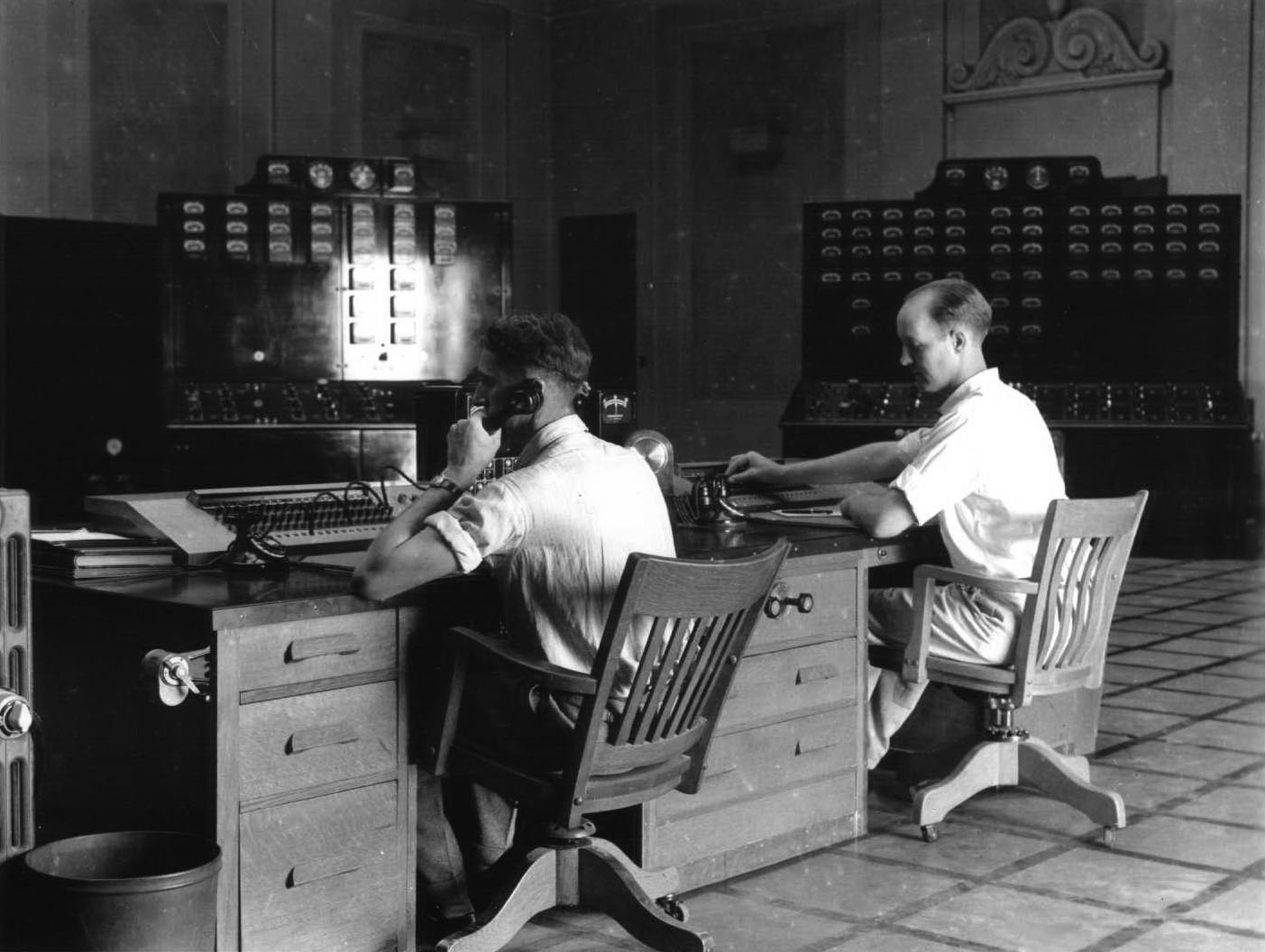
| (1936)^^ - Close-up view showing two operators sitting at the control desk at RS-B. |
From DWP's Historic Archives For maximum operating efficiency the most modern control and communication systems available have been installed. This equipment, costing $430,000, provides control of automatic relays that operate in split-second speed to clear line faults; gives supervisory control of switching operations at stations 90 and 180 miles from the Power Plant; keeps switching stations, local load dispatchers office, and operators at Boulder in constant telephonic communication by a carrier current system and enables patrolmen with radio equipped automobiles to receive instructions along the power line route similarly to radio police methods. |
 |
|
| (1936)^^ - A station operator standing in front of the control board for 34.5-kV Section C at RS-B. |
From DWP's Historic Archives Indicating lamps in the local dispatchers’ office will show at all times the open or closed positions of switches throughout the entire transmission system. Patrol cars will cover the 266 mile route daily and specially equipped trucks will be stationed at intermediate points to made emergency repairs that may be required. At Boulder City, 27 additional residences are being planned to house employees there, bringing to 66 the total number of houses and dormitories required for operating employees and their families at Boulder City, Silver Lake and Victorville. |
 |
|
| (1942)^^ - View showing a protective enclosure around one of the Boulder Banks at RS-B, made of heavy timbers to protect them from enemy attack during WWII. Photo Date: 2-27-42 |
 |
|
| (1947)^^ - Night shot of one of the Boulder Banks at RS-B. |
* * * * * |
Industrial Stations |
.jpg) |
|
| (1943)^^ – View showing Industrial Station 160. Note the guard tower at the left. The 13.8-kV switchrack is behind the guard tower and part of the 132-kV equipment in on the right. |
Background Information IS-160 was a temporary war-era expedient Industrial Station built to serve the Synthetic Rubber Plant. It was located off Normandie Ave., north of Torrance Blvd, near present-day Receiving Station Halldale. Along with IS-141 (ALCOA Aluminum), it was fed directly from the 132-kV system out of RS-C and had several 13.8-kV Feeders to serve the Synthetic Rubber Plant and other nearby defense industries. To conserve steel during the war, the 13.8-kV switchrack was made of wood. |
 |
|
| (1943)^^ – View of part of the 132-kV equipment at IS-160. There is an oil circuit breaker in the center rear and part of one of the transformers can be seen at the right edge. |
.jpg) |
|
| (1943)^^ - Aerial close-up view of the wooden 13.8-kV switchrack at IS-160. |
Background Information IS-160 was finally taken out of service about 1975 with the wooden switchrack in use up to the end. |
.jpg) |
|
| (ca. 1943)^^ - Operator Roy Stoutsenberger in the control room. To his left is the 132-kV control board and in from of him is the 13.8-kV control board. Note the empty KWH meter sockets at the top of the 13.8-kV board; when these pictures were taken the station was still under construction. |
Click HERE to see more in Early Power Station Operations |
* * * * * |
Sylmar Converter Station |
The Sylmar Converter Station is one of the most important electric power facilities ever built for Los Angeles. Completed in 1969, it serves as the southern terminal of the Pacific DC Intertie, a high voltage direct current transmission system linking Southern California with the hydroelectric and wind energy resources of the Pacific Northwest. Through this system, electricity generated hundreds of miles away in Oregon and Washington can be delivered efficiently into the Los Angeles power grid.The transmission line extends roughly eight hundred miles between the two regions and can carry about 3,100 megawatts of electricity, an amount often described as enough power to serve roughly three million homes. By operating at extremely high voltage, the system moves large amounts of electric power with relatively low losses. Unlike most long distance transmission lines that use alternating current and three conductors, the DC intertie uses two conductors operating at about plus and minus five hundred thousand volts, with converter stations at each end that change alternating current into direct current for transmission and then convert it back again for local use.When the project was designed in the nineteen sixties, engineers recognized that transmitting such large amounts of electricity over long distances using conventional alternating current would be difficult and inefficient. High voltage direct current offered a better solution, allowing greater stability, fewer losses, and precise control over the flow of power. One of the system’s most important features is that electricity can move in either direction, depending on seasonal demand.The Pacific DC Intertie is a shared transmission system owned by several western utilities, including the Bonneville Power Administration, the Los Angeles Department of Water and Power, Southern California Edison, and the municipal utilities of Burbank, Glendale, and Pasadena. LADWP operates the southern portion of the system at the Sylmar Converter Station. Because the system is shared, the full transmission capacity is not dedicated to Los Angeles alone, but instead allows electricity to move efficiently between regions as conditions change. |
 |
|
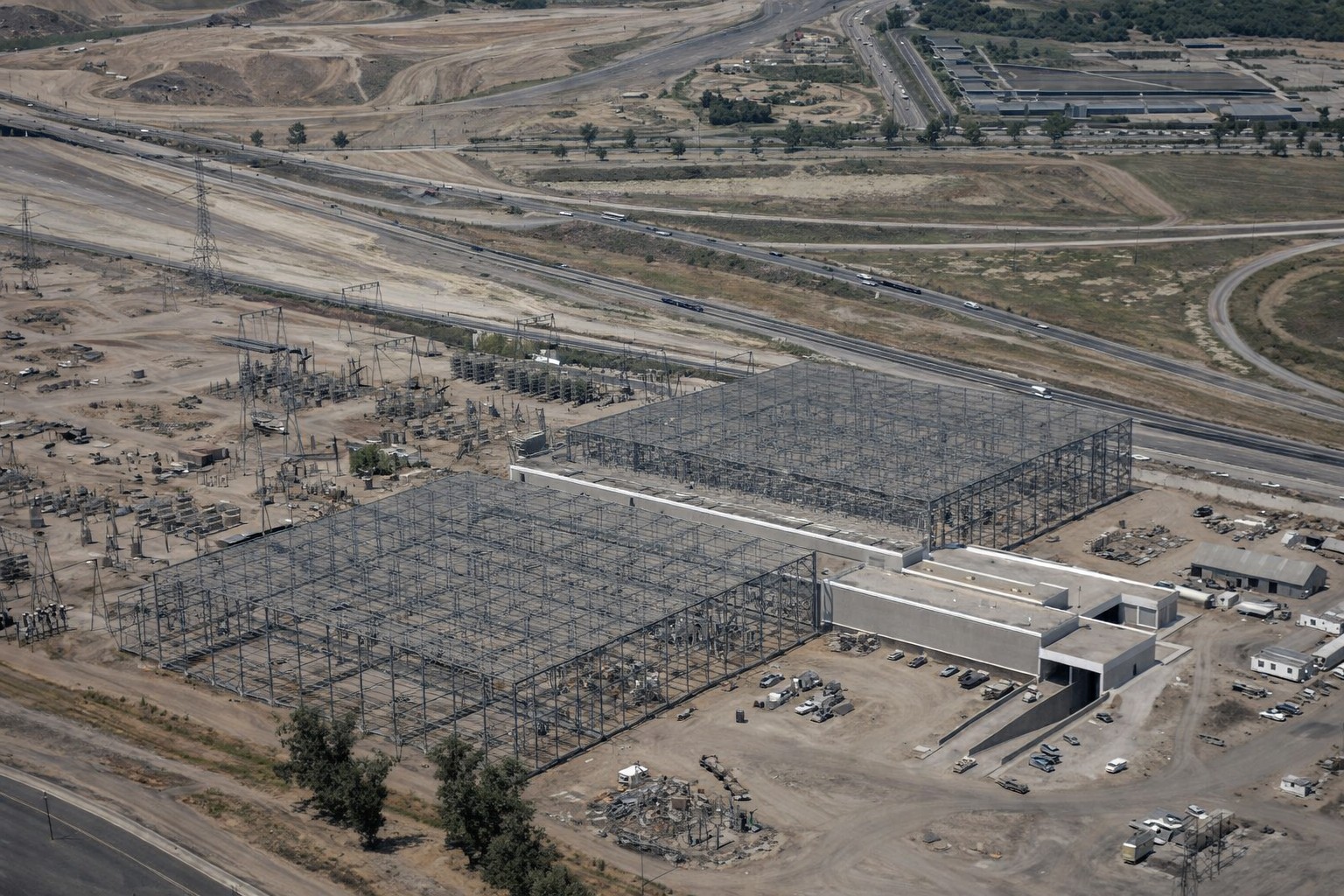
| (1969)* – Aerial view looking northeast showing the original Sylmar Converter Station west of Interstate 5 shortly after completion. Interstate 5 runs diagonally in the distance, with a portion of the Van Norman Reservoir visible at lower left. Photo date: July 18, 1969. |
| Historical Notes
By the summer of 1969 the original Sylmar Converter Station was nearing completion. Built west of Interstate 5, the facility formed the southern end of an approximately eight hundred mile high voltage direct current transmission line connecting Los Angeles with hydroelectric resources in Oregon and Washington. At the time it was built the Pacific DC Intertie represented one of the most advanced electric transmission systems in the world. By operating at extremely high voltage the line could carry large blocks of power over very long distances with relatively low losses. This view shows the station in its original location near the Van Norman Reservoir. Less than two years later the San Fernando earthquake would heavily damage the facility and surrounding infrastructure, altering the future of the site. |
 |
|
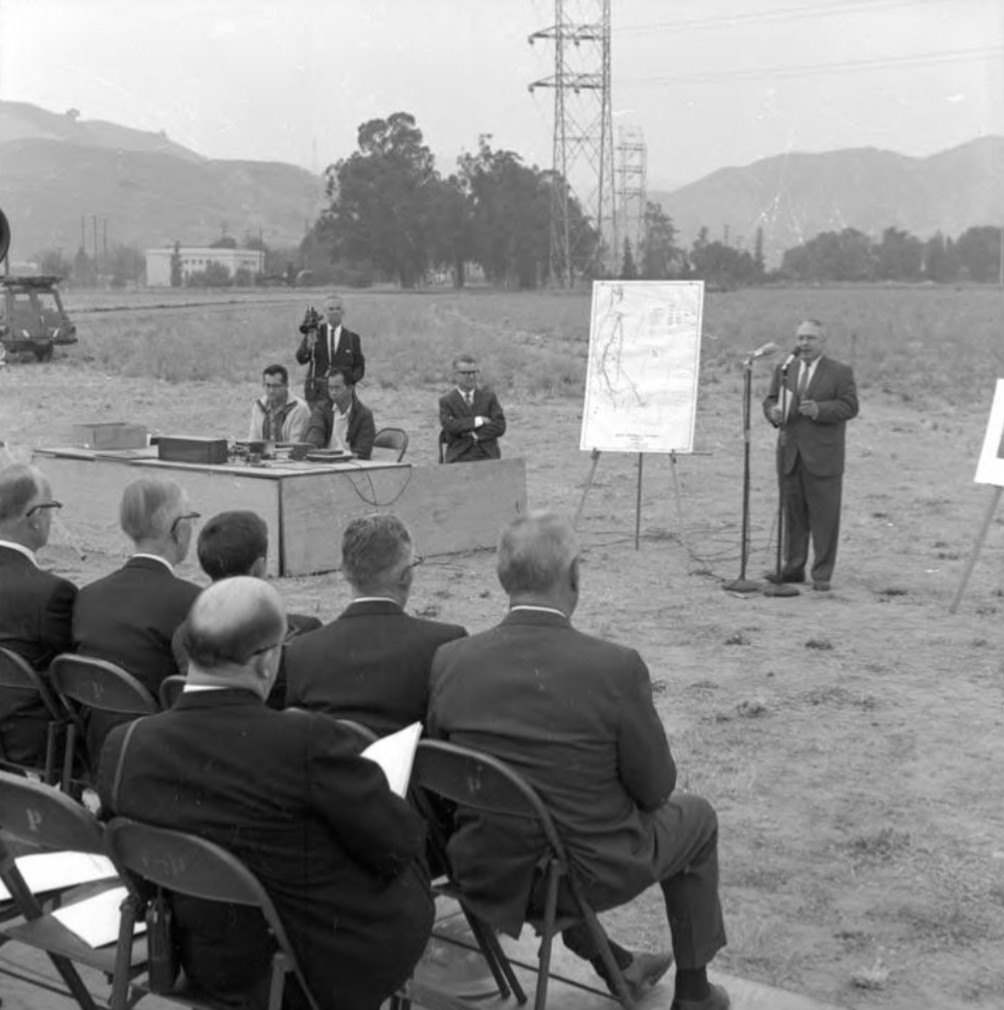
| (1967)* - Groundbreaking ceremony for the Sylmar Converter Station at its original site west of Interstate 5. Los Angeles Department of Water and Power General Manager E. L. Kanouse stands at the microphone. Photo date: June 8, 1967. |
| Historical Notes
Construction officially began in June 1967 on land west of Interstate 5. Los Angeles Department of Water and Power General Manager E L Kanouse emphasized the importance of the project in securing a stable and diversified power supply for the growing city. The converter station represented a major investment in long distance electric transmission. Direct current technology allowed large blocks of electricity to move efficiently between regions while giving operators precise control over the amount and direction of power entering Southern California. |
 |
|
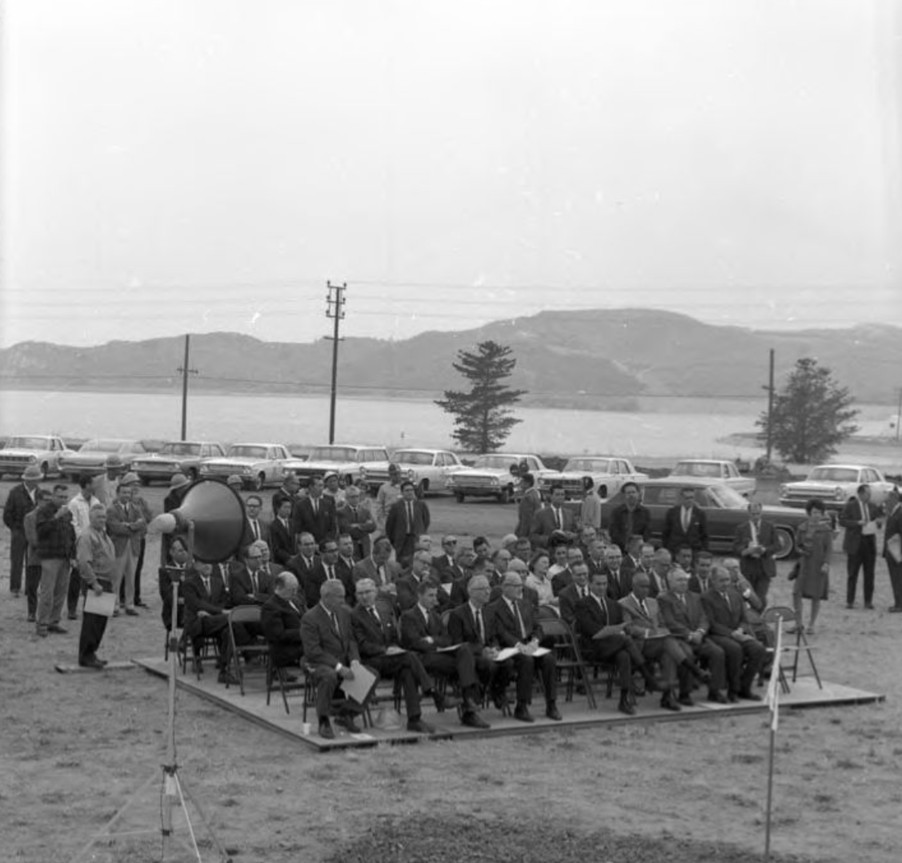
| (1967)* - Groundbreaking ceremony at the future site of the original Sylmar Converter Station. The Van Norman Reservoir appears in the background. |
| Historical Notes
This photograph shows the undeveloped site before construction began. The Van Norman Reservoir is visible behind the future station location, illustrating how closely the original installation was tied to the reservoir complex. That proximity became significant during the February 9, 1971 San Fernando earthquake, when severe ground shaking and reservoir damage contributed to major impacts at the converter facility. |
 |
|
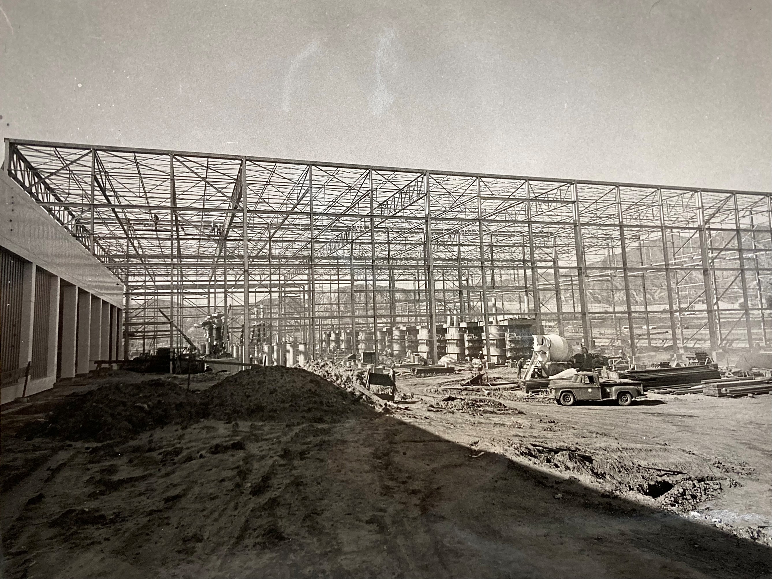
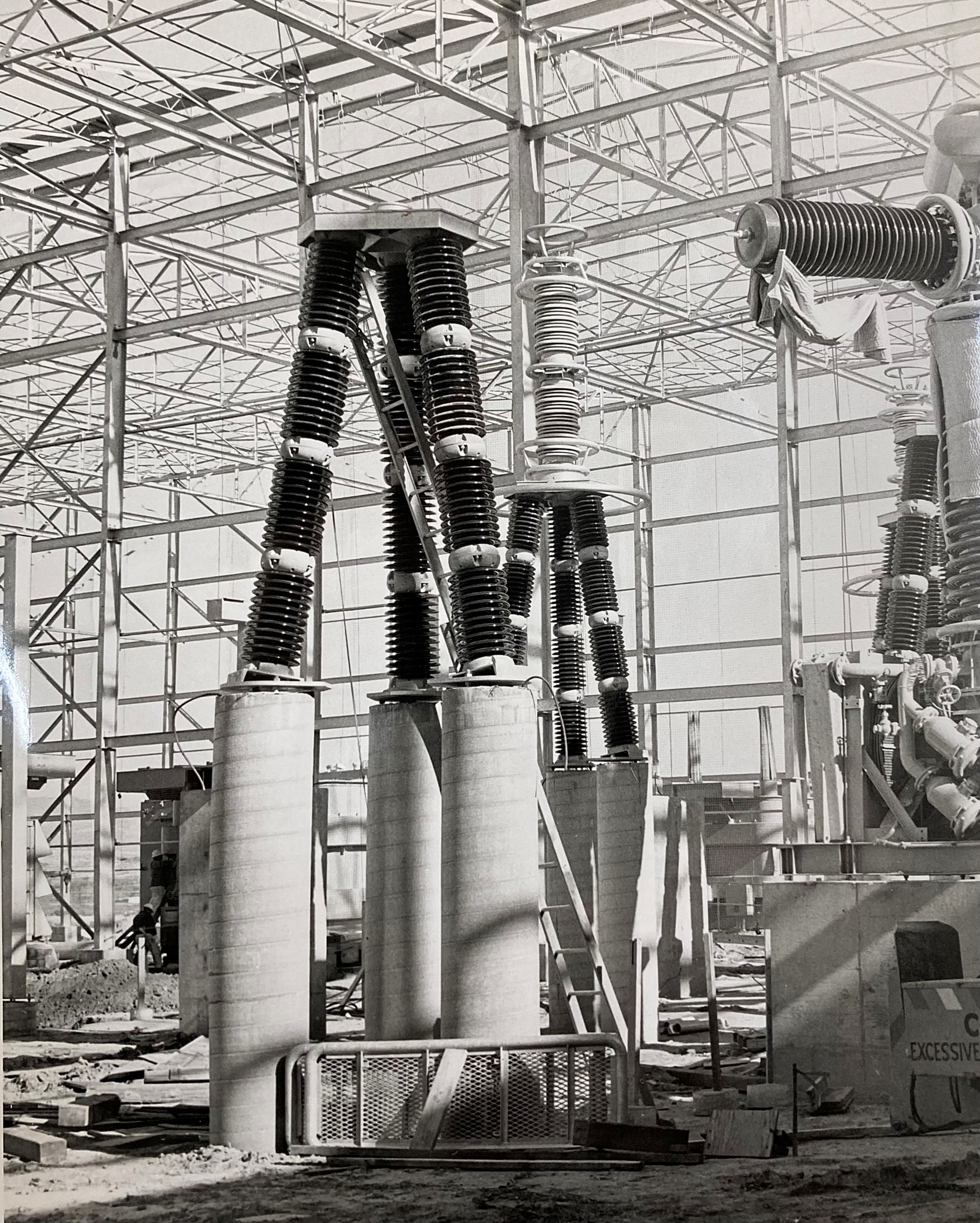
| (1969) - Installation of high voltage breakers and switches inside one of the original station’s enclosed valve halls. Photo courtesy of Craig Baker. |
| Historical Notes
Inside the original station massive breakers and switching equipment were installed to manage extremely high voltages and currents. These components protected the system by isolating electrical faults and allowing sections of the transmission system to be safely shut down for maintenance. The enclosed valve halls housed the conversion equipment that formed the heart of the Pacific DC Intertie southern terminal. Within these halls alternating current from the Los Angeles power system was converted to direct current for transmission and incoming direct current power was converted back to alternating current for distribution. The scale and complexity of the installation reflected the advanced engineering required to move electricity efficiently over hundreds of miles. |
 |
|
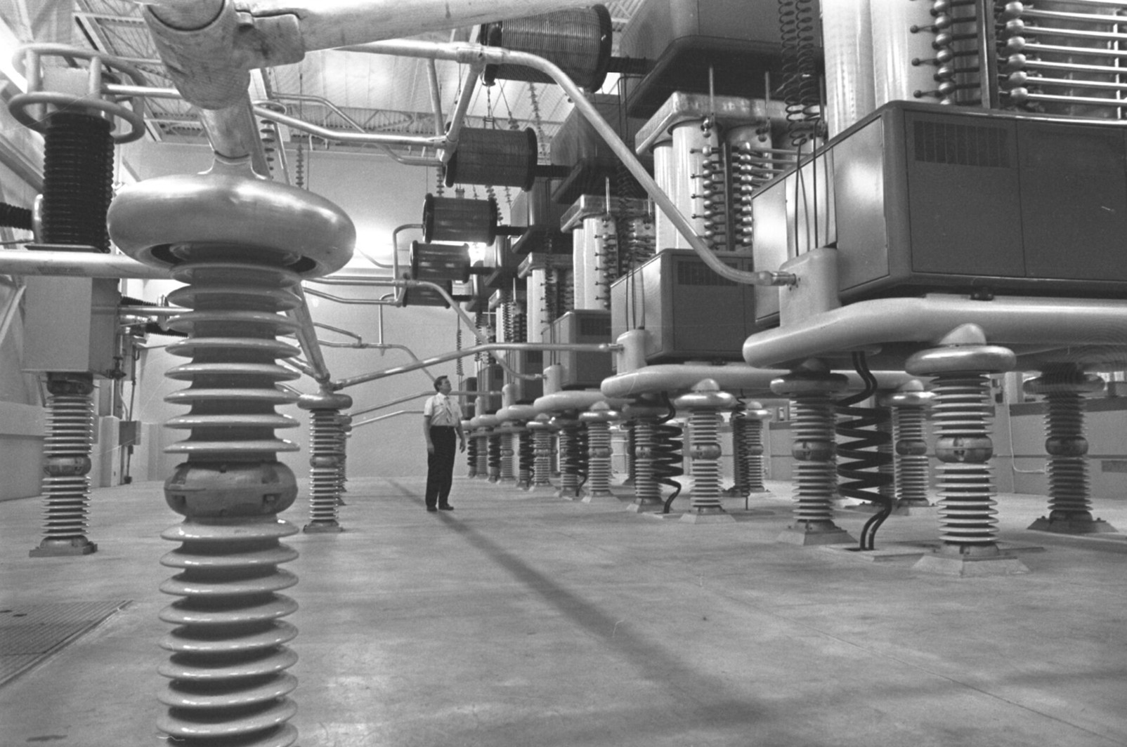
| (1969) – Assembly of inverter equipment within the original Sylmar Converter Station. Photo courtesy of Craig Baker. |
| Historical Notes
The inverter equipment was responsible for converting incoming direct current electricity into alternating current that could be distributed throughout the Los Angeles power grid. When the station first opened this conversion was performed by large mercury arc valves, which represented the most advanced power electronics technology of the era. These towering devices handled enormous amounts of electric power flowing through the transmission system. Their careful assembly and testing ensured that the Pacific DC Intertie could enter commercial service around 1970. |
 |
|
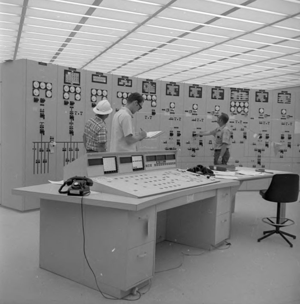
| (1969)* - Back to back testing in the original Sylmar Converter Station control room prior to full operation. Photo date: September 9, 1969. |
| Historical Notes
Before the system entered commercial operation, engineers conducted extensive testing to ensure stable and synchronized performance. Back to back testing allowed the converters to operate under controlled conditions before the full transmission link was energized. The ability to precisely regulate power flow was one of the key advantages of direct current transmission. This feature strengthened reliability across the western grid and allowed Los Angeles to manage imported power efficiently. |
 |
|
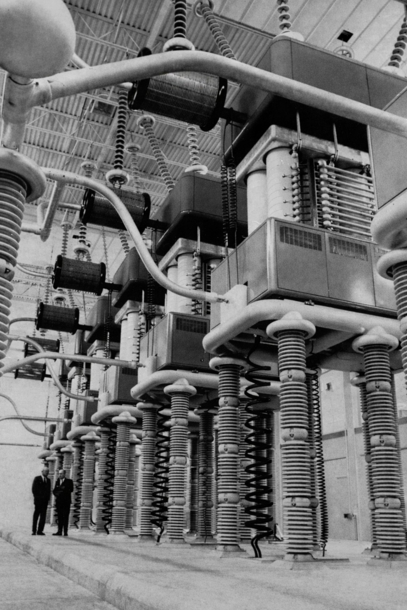
| (1970)* - Worker standing beside one of the giant mercury arc valves inside the original Sylmar Converter Station west of Interstate 5. |
| Historical Notes
The enormous mercury arc valves towered above workers inside the facility. These glass and steel devices converted electricity between alternating current and direct current and formed the technological core of the converter station. At the time of its construction the Sylmar installation attracted international attention among electrical engineers. The converter equipment and mercury arc valves used at the station were among the largest ever built. When the system entered service around 1970 it quickly became one of the most important and largest high voltage direct current transmission systems in the world, serving as a model for similar projects developed later in Europe and Asia. The Sylmar Converter Station served as the southern gateway through which power from the Pacific Northwest could enter the Los Angeles power grid. |
 |
|
| (ca. 1972)* – View of rebuilt D.C. inverter units following restoration work after the 1971 San Fernando earthquake. Two workers provide scale. |
| Historical Notes
On February 9, 1971 the San Fernando earthquake caused severe damage throughout the Sylmar area, including at the converter station and the nearby Van Norman Reservoir complex. Powerful ground shaking displaced equipment and damaged structures within the facility. This photograph shows rebuilt inverter equipment following restoration work after the earthquake. The two workers standing nearby provide a sense of scale for the massive electrical components. Although the station was repaired and strengthened, the earthquake revealed vulnerabilities in the original west side location. In the decades that followed engineers expanded and modernized the facility while planning a more seismically secure converter station east of Interstate 5. |
 |
|
| (2013)* – The rebuilt and modernized Sylmar Converter Station located east of Interstate 5. This facility assumed full operation in 2004 and was rededicated in 2005. |
| Historical Notes
In 2004 a newly rebuilt and modernized converter station east of Interstate 5 assumed the full electrical load of the Pacific DC Intertie. The facility incorporated advanced solid state power electronics along with improved seismic engineering and modern control systems. The station was formally rededicated in 2005 as the Sylmar Converter Station, replacing the original west side installation. Today it remains a vital component of the western power grid, allowing electricity to move between Southern California and the Pacific Northwest and helping ensure reliable electric service across the region. |
* * * * * |
History of Water and Electricity in Los Angeles
More Historical Early Views
Newest Additions
Early LA Buildings and City Views
* * * * * |
References and Credits
* DWP - LA Public Library Image Archive
**Library of Congress Digital Archive
^^DWP - Water and Power Associates Historical Archives - Courtesy of Rex Atwell
*^Southland.Gizmodo.com: LA's Power Grid
*#Moving LADWP High Voltage Around
**^Wikipedia: Electrical Substation
< Back